How to Choose the Right AV Cable Type for Signal Flow Diagrams
In professional audiovisual (AV) installations, selecting the right av cable types can mean the difference between a flawless system and one plagued by signal degradation, compatibility issues, and costly troubleshooting. Every AV system integrator, consultant, and installation technician faces critical decisions about cable specifications, connector compatibility, and signal transmission requirements that directly impact system performance, reliability, and long-term maintainability.
Understanding av cable types extends far beyond simply knowing HDMI from SDI—it requires comprehensive knowledge of signal formats, bandwidth limitations, distance constraints, interference susceptibility, and application-specific requirements that vary dramatically across corporate boardrooms, broadcast studios, houses of worship, educational facilities, and entertainment venues.
Choosing the best software to design audio visual (AV) equipment racks becomes equally critical when managing the complexity of modern AV cable infrastructure. Professional AV design software like XTEN-AV enables system designers to document cable specifications, generate comprehensive cable schedules, maintain accurate as-built records, and ensure installation teams have the precise information needed to implement systems correctly the first time.
This comprehensive guide explores the different types of AV cables used in professional installations, detailing their technical characteristics, optimal applications, distance limitations, and best practices for cable selection and documentation. Whether you're designing a simple conference room or a complex broadcast facility, understanding these cable types and their appropriate applications is fundamental to delivering reliable, high-performance AV systems.
Key Takeaways
Before exploring specific av cable types and their applications, here are the essential points every AV professional should understand:
Different av cable types serve specific purposes—video cables, audio cables, control cables, network cables, and power cables each have distinct technical specifications and optimal use cases
Signal format requirements dictate cable selection: 4K60 4:4:4 requires different bandwidth than 1080p, uncompressed audio needs different cables than compressed formats
Distance limitations vary dramatically across cable types: HDMI typically maxes at 15 meters, SDI reaches 100+ meters, fiber optic extends to kilometers
Professional-grade cables differ significantly from consumer versions in build quality, shielding effectiveness, connector durability, and performance consistency
Cable infrastructure planning must account for future requirements, not just current needs—bandwidth headroom prevents premature obsolescence
Proper cable documentation using tools like XTEN-AV reduces installation errors by 70-80% and dramatically improves troubleshooting efficiency
Hybrid cable solutions combining power, video, audio, and control in single runs can simplify installations while reducing cable pathway congestion
Interference management through proper cable selection, routing, and shielding prevents signal degradation in electrically noisy environments
Standardized cable labeling and comprehensive cable schedules are essential for professional installations that require long-term maintenance and future modifications
What Are AV Cables?
AV cables are specialized transmission media designed to carry audio signals, video signals, control data, network traffic, or electrical power between components in audiovisual systems. Unlike generic electrical wiring, professional AV cables are engineered to meet specific performance requirements for signal integrity, bandwidth capacity, distance capabilities, and interference rejection.
Core Functions of AV Cables
Professional AV cables serve four primary functions in integrated systems:
Signal Transmission: Carrying audio waveforms, video data, or control commands from source devices to destination equipment while maintaining signal quality and timing accuracy.
Power Distribution: Delivering electrical power to active devices, amplifiers, display panels, and network switches that require AC or DC power.
Data Communication: Transporting digital data packets, network traffic, control protocols, and metadata that enable system intelligence and remote management.
System Integration: Providing the physical connectivity that binds discrete components into cohesive systems capable of coordinated operation and centralized control.
Professional vs. Consumer Cable Distinctions
Professional AV cables differ from consumer-grade alternatives in critical ways:
Construction Quality: Professional cables use higher-grade conductors, superior shielding materials, reinforced strain reliefs, and precision-manufactured connectors that withstand repeated installation, environmental stress, and long-term use.
Performance Specifications: Pro-grade cables meet documented specifications for bandwidth, return loss, crosstalk, attenuation, and jitter that consumer cables may not consistently achieve.
Certification and Testing: Professional cables often carry manufacturer certifications, third-party testing verification, and warranty coverage that provide performance assurance for critical installations.
Availability and Support: Professional cable manufacturers maintain consistent product lines, provide technical support, publish detailed specifications, and support large-scale procurement for commercial projects.
Why AV Cable Selection Matters in Professional Installations
Performance Impact
Cable selection directly affects system performance in measurable ways:
Signal Quality: Inadequate cable bandwidth, insufficient shielding, or excessive cable length causes signal degradation, sparkles in video, dropouts in audio, or complete signal failure.
System Reliability: Poor-quality cables introduce intermittent failures, temperature-sensitive problems, and connector failures that generate service calls and client dissatisfaction.
Feature Availability: Insufficient cable bandwidth prevents advanced features like 4K video, HDR, high frame rates, or uncompressed audio from functioning even when equipment supports them.
Cost Implications
Cable decisions have significant financial impact:
Initial Installation Costs: Premium cables cost more upfront, but cable failures requiring replacement in finished spaces cost exponentially more than initial quality investment.
Labor Efficiency: Proper cable selection enables first-time-right installations, while wrong cables cause rework, delays, and wasted labor that destroys project profitability.
Lifecycle Costs: Future-proof cable infrastructure supports system upgrades without cable replacement, while inadequate cables force complete re-cabling during technology refreshes.
Documentation and Maintenance
Cable selection affects long-term system management:
Troubleshooting Complexity: Well-documented cable types enable rapid problem diagnosis, while unknown or undocumented cables turn troubleshooting into guesswork.
Modification Planning: Documented cable specifications inform system expansion decisions, while unknown cable capabilities require expensive testing or conservative assumptions.
Standards Compliance: Proper cable selection ensures code compliance, warranty validity, and insurance coverage, while substandard cables create liability risks.
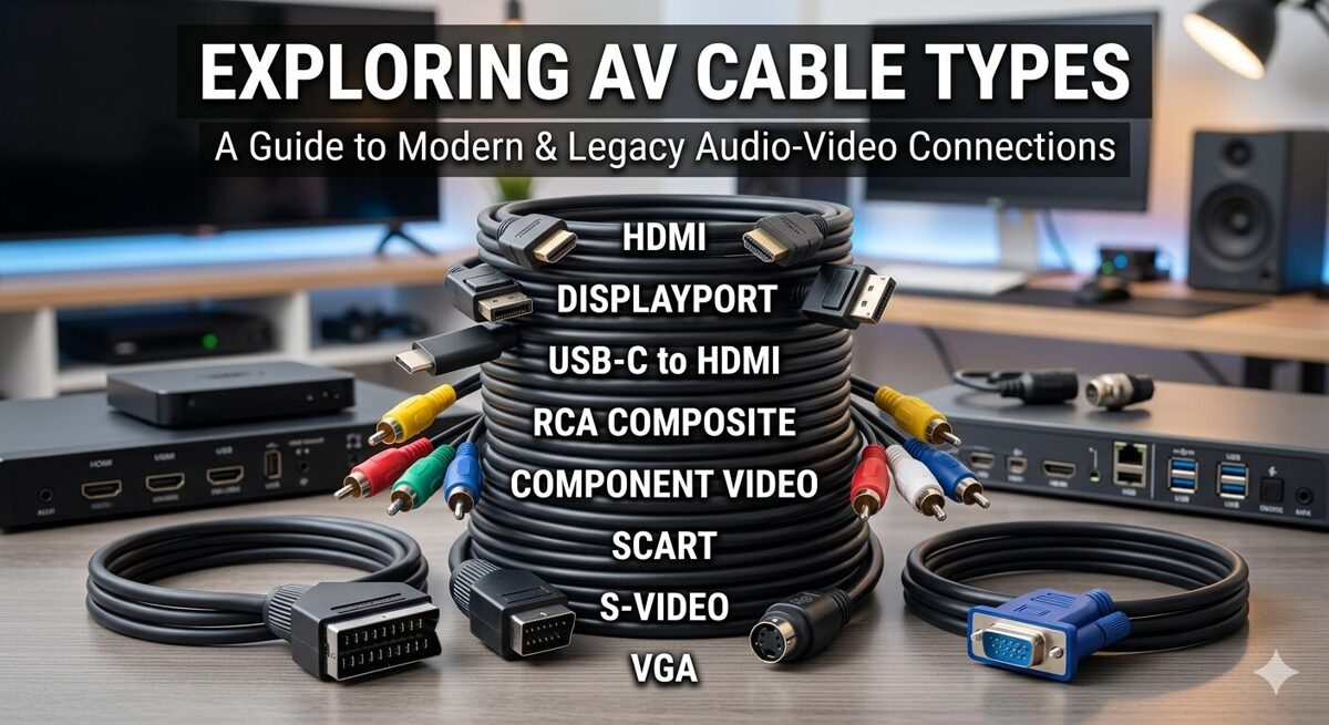
Types of AV Cables Used in AV Systems
HDMI Cables
HDMI (High-Definition Multimedia Interface) cables dominate consumer and commercial AV installations for digital video and audio transmission.
Technical Characteristics
HDMI cables carry uncompressed digital video, multi-channel audio, control data (CEC), and Ethernet over a single connection:
Bandwidth ranges: Standard HDMI (4.95 Gbps), High Speed (10.2 Gbps), Premium High Speed (18 Gbps), Ultra High Speed (48 Gbps)
Resolution support: Up to 10K at 120Hz with Ultra High Speed HDMI 2.1
Audio formats: Dolby Atmos, DTS:X, uncompressed PCM up to 32 channels
Connector types: Type A (standard), Type C (mini), Type D (micro)
Distance Limitations
HDMI distance capabilities vary by cable quality and signal format:
Standard copper HDMI: 5-15 meters for 4K signals, up to 25 meters for 1080p
Active HDMI cables: 20-30 meters with built-in signal amplification
HDMI over fiber: 100+ meters using fiber optic transmission
HDMI extenders: Unlimited distance using HDBaseT or IP-based transmission
Professional Installation Applications
HDMI cables appear in numerous professional scenarios:
Corporate Conference Rooms: Connecting laptops, wireless presentation systems, and displays for meeting collaboration
Digital Signage: Linking media players to commercial displays in retail, hospitality, and transportation environments
Education Spaces: Connecting document cameras, computers, and projectors in classrooms and lecture halls
Home Theaters: Professional residential installations requiring high-bandwidth video and immersive audio
Selection Considerations
When specifying HDMI cables for professional installations:
Verify bandwidth requirements match source resolution and frame rate
Choose certified Premium High Speed or Ultra High Speed cables for 4K/8K applications
Consider active cables or extenders for distances beyond 15 meters
Specify locking connectors for permanent installations to prevent accidental disconnection
Document HDMI version and bandwidth rating in cable schedules
DisplayPort Cables
DisplayPort cables offer an alternative digital video interface with advantages in computer-based AV systems and multi-display configurations.
Technical Characteristics
DisplayPort provides high-bandwidth digital transmission:
Bandwidth: Up to 80 Gbps with DisplayPort 2.0
Resolution support: 8K at 60Hz, 4K at 144Hz, multi-stream transport for daisy-chaining displays
Audio support: Multi-channel digital audio similar to HDMI
Connector types: Full-size DisplayPort, Mini DisplayPort
Professional Applications
DisplayPort cables excel in specific professional scenarios:
Command and Control Centers: Multi-monitor workstations requiring high-resolution displays and daisy-chain configurations
Medical Imaging: High-resolution diagnostic displays demanding color accuracy and high bandwidth
Broadcast Graphics: Video editing workstations and graphics systems requiring high refresh rates
Corporate Trading Floors: Multi-display trader workstations with dense display arrays
DisplayPort vs. HDMI
Key differences inform cable selection:
DisplayPort supports daisy-chaining multiple displays from single output
HDMI has broader consumer device compatibility
DisplayPort offers higher bandwidth in latest versions
HDMI includes CEC control and ARC audio return
USB-C Cables
USB-C cables increasingly appear in professional AV installations as unified connectivity solutions.
Technical Characteristics
USB-C combines multiple functions in single cables:
Data transfer: Up to 40 Gbps with USB4 and Thunderbolt 4
Video transmission: DisplayPort Alt Mode supports 4K and 8K video
Power delivery: Up to 240W for device charging and powering
Reversible connector: User-friendly connection without orientation concerns
Professional Applications
USB-C cables serve modern AV workflows:
BYOD Conference Rooms: Single-cable connections for laptops providing video, audio, data, and charging
Presentation Systems: USB-C docking solutions for simplified connectivity
Mobile Device Integration: Connecting tablets and smartphones to professional displays
Hybrid Work Spaces: Hot-desking environments requiring quick, universal connections
Selection Considerations
USB-C cable specifications vary widely:
Verify USB-C cable supports required functions (power delivery, video, data speeds)
Confirm power delivery rating meets device requirements
Check video Alt Mode support and resolution capabilities
Specify certified Thunderbolt cables when Thunderbolt compatibility required
VGA Cables
VGA (Video Graphics Array) cables remain in legacy installations despite being analog technology.
Technical Characteristics
VGA transmits analog RGB video:
Resolution support: Typically up to 1920×1200, though signal quality degrades at high resolutions
Analog transmission: Susceptible to interference and signal degradation
Separate audio: Requires additional audio cables
15-pin DE-15 connector: Standard VGA connector
Current Applications
VGA cables appear in:
Legacy System Support: Older projectors and displays without digital inputs
Industrial Control Systems: Older equipment in manufacturing and process control
Budget-Conscious Installations: Cost-sensitive projects with modest resolution requirements
Migration Strategies
Professional integrators should:
Plan VGA phase-out during system upgrades
Use active VGA-to-HDMI converters for legacy device integration
Document VGA cables as temporary solutions requiring future replacement
DVI Cables
DVI (Digital Visual Interface) cables bridge analog and digital video in transitional installations.
Technical Characteristics
DVI comes in multiple variants:
DVI-D: Digital-only transmission
DVI-A: Analog-only transmission
DVI-I: Integrated analog and digital
Single-link: Up to 1920×1200 at 60Hz
Dual-link: Up to 2560×1600 at 60Hz
Professional Applications
DVI cables appear in:
Older Computer Systems: Workstations and servers with DVI outputs
Professional Displays: Broadcast monitors and reference displays with DVI inputs
Medical Imaging: Legacy diagnostic displays requiring DVI connections
SDI Cables
SDI (Serial Digital Interface) cables are the professional broadcast standard for uncompressed digital video.
Technical Characteristics
SDI provides broadcast-quality video transmission:
SD-SDI: Standard definition (270 Mbps)
HD-SDI: 1080i/720p (1.485 Gbps)
3G-SDI: 1080p (2.97 Gbps)
6G-SDI: 4K at 30Hz (6 Gbps)
12G-SDI: 4K at 60Hz (12 Gbps)
BNC connectors: Professional locking connectors
75-ohm coaxial cable: Broadcast-standard impedance
Distance Capabilities
SDI excels at long-distance transmission:
HD-SDI: 100+ meters on quality coax
3G-SDI: 70-100 meters depending on cable quality
12G-SDI: 50-70 meters on premium cables
SDI fiber: Kilometers using fiber optic transmission
Professional Applications
SDI cables dominate professional video:
Broadcast Studios: Camera feeds, router connections, monitor distribution
Live Production: Mobile production trucks, event coverage, multi-camera productions
Post-Production Facilities: Editing suites, color grading, video processing
Houses of Worship: Professional video production in large worship facilities
Sports Venues: Camera systems, replay systems, video distribution
Selection Considerations
SDI cable selection requires attention to:
Match SDI format to signal bandwidth (HD, 3G, 6G, 12G)
Use quality coaxial cable with proper impedance (75 ohms)
Specify precision BNC connectors with proper crimping
Consider fiber SDI for distances beyond copper limits
Document SDI format and cable length in system documentation
RCA Cables
RCA cables (also called phono cables or composite video cables) carry analog audio and video signals.
Technical Characteristics
RCA cables use coaxial construction:
Composite video: Single RCA connector (yellow) for analog video
Analog stereo audio: Two RCA connectors (red/white) for left/right channels
Component video: Three RCA connectors (red/green/blue) for higher-quality analog video
Unbalanced audio: Susceptible to noise over long distances
Professional Applications
RCA cables appear in:
Legacy Audio Systems: Older audio equipment without balanced connections
Consumer Device Integration: Connecting consumer media players to professional systems
DJ Equipment: Turntables and DJ mixers often use RCA connections
Background Music Systems: Simple audio distribution in retail and hospitality
Professional Alternatives
Professional installations typically favor:
XLR balanced audio instead of RCA unbalanced
SDI or HDMI instead of composite/component video
Digital audio instead of analog RCA
XLR Cables
XLR cables are the professional standard for balanced analog audio transmission.
Technical Characteristics
XLR cables provide balanced audio connections:
Three-pin configuration: Pin 1 (ground), Pin 2 (positive), Pin 3 (negative)
Balanced transmission: Common-mode noise rejection for clean audio
Microphone-level and line-level support
Professional locking connectors: Prevent accidental disconnection
Phantom power capability: Delivers 48V for condenser microphones
Distance Capabilities
XLR balanced audio excels at long runs:
Microphone-level: 100+ meters without significant degradation
Line-level: 300+ meters with proper cable quality
Noise immunity: Balanced design rejects electromagnetic interference
Professional Applications
XLR cables dominate professional audio:
Live Sound Systems: Microphone connections, mixer outputs, speaker feeds (though Speakon increasingly used for speakers)
Broadcast Studios: Microphone feeds, audio routing, intercom systems
Houses of Worship: Vocal microphones, instrument connections, audio distribution
Conference Rooms: Ceiling microphones, wireless microphone receivers, DSP connections
Recording Studios: Microphone connections, outboard gear, monitor feeds
Cable Quality Considerations
Professional XLR cables require:
High-quality shielding for noise rejection
Precision connectors (Neutrik, Switchcraft) for reliability
Proper cable gauge for application (thinner for microphones, heavier for long runs)
Strain relief to prevent connector failure
Speaker Cables
Speaker cables carry high-power audio signals from amplifiers to loudspeakers.
Technical Characteristics
Speaker cables handle high current:
Low impedance: Typically 4-8 ohms
High current capacity: Amplifier power converted to current
Conductor gauge: 12 AWG to 18 AWG typical, heavier for high power or long runs
Connector types: Bare wire, banana plugs, spade lugs, Speakon connectors
Distance and Gauge Relationships
Cable gauge affects signal loss:
Short runs (under 15m): 16-18 AWG acceptable
Medium runs (15-30m): 14-16 AWG recommended
Long runs (30m+): 12-14 AWG or heavier
High-power systems: Use heavier gauge regardless of distance
Professional Applications
Speaker cables connect:
Installed Sound Systems: Ceiling speakers, wall-mounted speakers, pendant speakers
Performance Venues: Line arrays, stage monitors, subwoofers
Houses of Worship: Main speakers, delay speakers, choir monitors
Corporate AV: Conference room speakers, presentation audio
Speakon Connectors
Professional installations increasingly use Speakon connectors:
Locking mechanism: Prevents accidental disconnection
High current capacity: Handles kilowatts of amplifier power
Multiple configurations: 2-pole, 4-pole, 8-pole for bi-amp and multi-way systems
Industry standard: Live sound and installed sound applications
Ethernet Cables for AV-over-IP
Ethernet cables enable AV-over-IP systems, control networks, and device connectivity.
Technical Characteristics
Ethernet cables for AV applications:
Cat5e: 1 Gbps, adequate for compressed AV and control
Cat6: 1 Gbps (up to 10 Gbps short runs), common for AV-over-IP
Cat6a: 10 Gbps at 100 meters, preferred for uncompressed 4K AV-over-IP
Cat7/Cat8: Higher frequencies and shielding for demanding applications
PoE capability: Delivers power to network devices (15W to 90W depending on PoE standard)
AV-over-IP Applications
Ethernet cables enable modern AV distribution:
Enterprise AV Systems: Networked video distribution, digital signage networks, unified communications
Broadcast IP Workflows: SMPTE ST 2110 and NDI video production
Control Systems: Crestron, Extron, AMX control networks
Dante Audio Networks: Networked audio distribution and processing
HDBaseT Systems: Video extension with power, control, and USB over single Cat cable
Selection Considerations
Ethernet cable selection for AV requires:
Cat6a minimum for 10G AV-over-IP and future-proofing
Solid conductors for permanent installations, stranded for patch cables
Proper termination to TIA-568A/B standards
Testing and certification for guaranteed performance
Shielded cables (STP/FTP) in high-interference environments
Fiber Optic AV Cables
Fiber optic cables provide ultra-long-distance transmission, immunity to interference, and massive bandwidth.
Technical Characteristics
Fiber optic cables use light transmission:
Single-mode fiber: Long distances (kilometers), higher cost, laser light sources
Multimode fiber: Shorter distances (300-550m), lower cost, LED light sources
OM3/OM4/OM5: Multimode grades for 10G/40G/100G transmission
LC, SC, ST connectors: Various connector types for different applications
Immune to EMI/RFI: Perfect for electrically noisy environments
Professional Applications
Fiber optic cables excel in:
Campus AV Distribution: Connecting buildings across large campuses
Stadium and Arena Systems: Long-distance video and audio distribution
Broadcast Facilities: SDI over fiber, SMPTE ST 2110 IP video
Data Centers: High-bandwidth AV switching and routing
Outdoor Installations: Weather-resistant and lightning-immune connections
Fiber vs. Copper Decision Factors
Choose fiber optic cables when:
Distance exceeds copper limits (typically 100m for Ethernet, 100m for SDI)
Electrical isolation required between buildings or zones
Electromagnetic interference prevents copper cable use
Bandwidth requirements exceed copper capabilities
Future-proofing demands maximum bandwidth headroom
Control and Serial Cables
Control cables carry low-speed data for system automation and device control.
Common Control Cable Types
RS-232 Serial: Point-to-point control for legacy devices (15m typical limit)
RS-422/RS-485: Multi-drop serial networks for longer distances (up to 1200m)
IR (Infrared) Cable: Extends IR remote control to equipment locations
Relay Control: Dry contact closure for simple on/off control
GPIO (General Purpose I/O): Digital control signals for custom integrations
Professional Applications
Control cables enable:
AV Control Systems: Crestron, AMX, Extron processor connections to controlled devices
Lighting Control: DMX512 for theatrical lighting and architectural lighting
HVAC Integration: AV systems controlling climate systems
Motorized Screen/Lift Control: Projector screens, display lifts, camera lifts
Security System Integration: AV systems triggering security responses
Power Cables in AV Installations
Power distribution is critical to AV system reliability.
AC Power Distribution
AC power cables in professional AV:
Edison (NEMA 5-15): Standard 120V 15A connections
NEMA 5-20: 120V 20A for higher-power devices
IEC C13/C14: Computer-style power for rack equipment
IEC C19/C20: Higher-current rack equipment
PowerCON: Locking power connectors for professional audio
Distro boxes: Multi-outlet power distribution for events and temporary installations
Low-Voltage DC Power
DC power distribution appears in:
PoE (Power over Ethernet): 15W to 90W over network cables
HDBaseT with PoE: Power and AV signals over single cable
12V/24V DC systems: LED lighting, small displays, control devices
USB power delivery: Up to 240W for device charging
Power Considerations
Professional power distribution requires:
Dedicated circuits for AV equipment separate from general building power
Proper grounding to prevent ground loops and noise
Surge protection and power conditioning for sensitive equipment
Load calculations ensuring circuits aren't overloaded
Emergency power planning for mission-critical systems
AV Cable Use Cases by Installation Type
Corporate Conference Rooms
Typical cable requirements:
HDMI/USB-C for laptop connections and wireless presentation
Cat6a Ethernet for AV-over-IP, control networks, PoE devices
XLR or Cat cable for ceiling microphones and DSP connections
Speaker cable for in-ceiling speakers or soundbars
Control cables for display control, motorized shades
Broadcast Studios
Professional broadcast cabling:
12G-SDI for 4K camera feeds and video routing
Fiber optic SDI for long-distance video between production areas
XLR balanced audio for microphones and audio routing
MADI or Dante for multi-channel digital audio
Intercom cables (Cat or dedicated) for production communication
Timing and sync cables for genlock and system synchronization
Houses of Worship
Worship facility cabling:
SDI or HDMI for camera systems and video distribution
XLR for vocal microphones, instrument connections, audio mixing
Speaker cable/Speakon for main PA, monitors, delay speakers
DMX512 for stage lighting control
Cat6a for video streaming, recording systems, control networks
Educational Facilities
Classroom and lecture hall cables:
HDMI for document cameras, computers, projectors
Cat6a for network connectivity, AV-over-IP distribution
USB extension for interactive displays and cameras
Audio cables for ceiling speakers and assistive listening systems
Control cables for touch panels, automated systems
Entertainment Venues
Theater and performance space cabling:
SDI for broadcast-quality video production
XLR and Speakon for professional audio systems
DMX512 for theatrical lighting
Fiber optic for long-distance signal distribution
Intercom systems for crew communication
Common AV Cable Selection Mistakes
Underestimating Bandwidth Requirements
Insufficient cable bandwidth causes:
4K signals failing on Standard HDMI or Cat5e
Future system upgrades requiring complete re-cabling
Compressed video where uncompressed was expected
Solution: Specify cables with bandwidth headroom beyond current needs.
Ignoring Distance Limitations
Exceeding cable distance limits results in:
Signal dropouts or complete failure
Image quality degradation (sparkles, color shifts)
Audio noise or signal loss
Solution: Use appropriate cable types for distances, add active extension when needed.
Mixing Cable Grades
Combining different cable qualities creates:
Inconsistent system performance
Difficult troubleshooting when some cables work and others fail
Premature system obsolescence limited by lowest-quality cables
Solution: Standardize on professional-grade cables throughout installations.
Poor Cable Management
Inadequate cable organization causes:
Difficult troubleshooting when cables aren't labeled
Accidental disconnections during maintenance
Airflow blockage in equipment racks
Solution: Implement proper cable management, labeling, and documentation.
Neglecting Environmental Factors
Ignoring installation environment leads to:
Cable degradation from UV exposure, moisture, temperature extremes
Interference problems from electrical noise sources
Physical damage from foot traffic, furniture, construction
Solution: Specify appropriate cable jackets, conduit protection, proper routing.
AV Cable Labeling and Documentation
Why Cable Labeling Matters
Proper cable identification provides:
Rapid troubleshooting when problems occur
Efficient modifications during system upgrades
Clear communication between installation crews and service technicians
Professional appearance that reflects quality workmanship
Effective Labeling Conventions
Professional cable labels should include:
Cable type (HDMI, Cat6a, XLR, etc.)
Source equipment identifier
Destination equipment identifier
Sequential number within cable type
Installation date or project identifier (optional)
Example labeling scheme: HDMI-SRC-DISP-01, CAT6-SW01-DSP-03, XLR-MIC-MIX-12
Cable Documentation Best Practices
Comprehensive cable documentation includes:
Cable schedules listing all cables with specifications
Rack elevation diagrams showing physical cable routing
Signal flow diagrams illustrating logical connections
As-built drawings reflecting actual installed conditions
FAQs
1. What are the most common av cable types used in professional AV installations?
The most common av cable types in professional installations include HDMI for digital video/audio, SDI for broadcast video, XLR for balanced audio, Cat6a Ethernet for AV-over-IP and control networks, speaker cables for audio systems, and fiber optic for long-distance transmission. The specific cable types depend on the application—corporate environments favor HDMI and Cat6a, while broadcast facilities rely heavily on SDI and fiber optic cables.
2. How do I choose between HDMI and SDI cables for video transmission?
Choose HDMI cables for distances under 15 meters, consumer device compatibility, and integrated audio/video transmission in corporate or education environments. Select SDI cables for longer distances (100+ meters), professional broadcast quality, multi-camera systems, and environments requiring robust, interference-resistant connections. SDI also offers better cable availability in professional lengths and more reliable locking BNC connectors compared to HDMI.
3. What is the maximum distance for different av cable types without signal loss?
Distance limitations vary significantly: HDMI copper cables typically max at 15 meters for 4K, SDI coaxial reaches 100+ meters for HD (less for 12G-SDI), Cat6a Ethernet extends to 100 meters for 10G, XLR balanced audio works well beyond 100 meters, fiber optic cables span kilometers, and USB-C typically limits to 3-5 meters for full functionality. For longer distances, use active cables, extenders, fiber optic alternatives, or AV-over-IP solutions.
4. Why are professional-grade AV cables more expensive than consumer versions?
Professional-grade cables cost more due to superior construction quality, higher-grade conductors, better shielding, precision-manufactured connectors, consistent performance specifications, durability testing, manufacturer certifications, and reliable warranty coverage. Consumer cables may work initially but often fail under repeated use, environmental stress, or demanding signal requirements. The higher initial cost of professional cables prevents expensive failures, service calls, and replacement costs in finished installations.
5. How important is cable labeling in professional AV installations?
Cable labeling is absolutely critical for professional installations. Proper labels reduce troubleshooting time by 60-70%, enable rapid system modifications, facilitate clear communication between installation crews and service technicians, and reflect professional workmanship. Unlabeled cables turn simple troubleshooting into time-consuming detective work and make future modifications extremely difficult. Use consistent labeling conventions that identify cable type, source, destination, and sequential numbers.
6. What cable types are best for future-proofing AV installations?
For future-proofing, specify Cat6a or Cat7 Ethernet for 10G+ bandwidth, Ultra High Speed HDMI 2.1 for 8K/10K video, 12G-SDI for broadcast applications, and OM3/OM4 multimode fiber or single-mode fiber for long-distance runs. Fiber optic cables offer the most future-proof solution with virtually unlimited bandwidth potential. Always install cable pathways with 40-50% spare capacity to accommodate additional cables during future upgrades without re-construction.
7. How does XTEN-AV improve AV cable documentation compared to manual methods?
XTEN-AV eliminates manual spreadsheet maintenance, version control problems, and drawing-schedule mismatches by maintaining all cable data in a unified database that automatically generates cable schedules, rack elevations, and documentation packages. Automated cable labeling ensures consistency, intelligent cable objects maintain relationships with equipment, and multi-view synchronization keeps all drawings current when changes occur. AV integrators report 40-60% time savings in documentation and 70-80% reduction in installation errors using XTEN-AV compared to manual methods.
Conclusion
Understanding the different types of AV cables and their appropriate applications is fundamental to delivering reliable, high-performance audiovisual systems. From HDMI and DisplayPort for digital video, to SDI for broadcast applications, XLR for professional audio, Cat6a for AV-over-IP networks, and fiber optic for long-distance transmission, each cable type serves specific purposes with distinct technical characteristics, distance limitations, and optimal use cases.
Professional AV integrators must consider multiple factors when selecting av cable types: signal format requirements, bandwidth needs, distance constraints, environmental conditions, interference susceptibility, connector compatibility, and future expansion requirements. Poor cable selection leads to signal degradation, system failures, costly rework, and client dissatisfaction, while proper cable specification ensures reliable performance, long-term maintainability, and future-proof infrastructure.
Cable documentation is equally critical to cable selection. Comprehensive cable schedules, accurate rack elevations, consistent labeling conventions, and detailed as-built records transform cable infrastructure from anonymous wiring into manageable, maintainable systems. XTEN-AV revolutionizes this documentation process by automating cable schedule generation, maintaining synchronized multi-view drawings, ensuring consistent labeling, and creating professional documentation packages that serve installation teams, service technicians, and facility managers throughout system lifecycles.
The AV industry continues evolving toward higher bandwidths, longer distances, IP-based distribution, and integrated control systems. Future-proof cable infrastructure requires strategic planning, quality components, and comprehensive documentation that supports system evolution without complete re-cabling. Cat6a Ethernet, fiber optic cables, and Ultra High Speed HDMI provide bandwidth headroom for emerging technologies, while proper cable pathways accommodate future additions.
Professional AV integrators who master cable type selection, implement consistent documentation practices, and leverage intelligent design tools like XTEN-AV position themselves as trusted partners delivering reliable, maintainable, future-proof systems. In an industry where cable problems account for 60-70% of commissioning delays and service calls, cable expertise and documentation excellence provide competitive advantages that translate directly to project profitability, client satisfaction, and long-term success.
Whether designing corporate conference rooms, broadcast studios, houses of worship, educational facilities, or entertainment venues, understanding av cable types and their professional applications remains fundamental to AV system integration excellence.
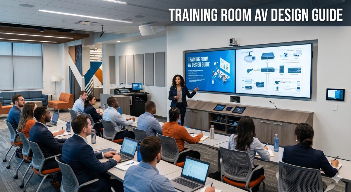
The Ultimate Training Room AV Design Guide for Businesses, Schools, and Training Centers
In June 2026, designing effective training room AV systems has become essential across businesses, schools, and training centers, as each sector recognizes that quality learning environments directly impact knowledge retention, participant engagement, and organizational success. Whether you're an AV integrator, system designer, or technology consultant, understanding how to create training room AV systems that serve the unique requirements of corporate training, educational instruction, and professional development is critical for delivering solutions that meet diverse learning objectives, budget constraints, and operational needs. This comprehensive guide explores the specialized requirements across all three sectors, covering sector-specific design principles, technology selection criteria, best practices, and professional tools like XTEN-AV X-Draw that enable AV professionals to efficiently deliver tailored training environments for any organization type.
Training room AV systems are integrated audio-visual solutions designed to support learning activities through display technology, audio reinforcement, video capture, content sharing, and control automation, with specific configurations optimized for corporate training, K-12/higher education, or professional development centers.
Key Takeaways
Before exploring the sector-specific requirements for training room AV systems, here are the essential concepts every AV professional should understand:
Businesses, schools, and training centers share common technology foundations but require distinct design approaches based on usage patterns and user types
Corporate training rooms prioritize ROI metrics, hybrid capabilities, simplified operation, and integration with enterprise IT systems
Educational environments emphasize durability, accessibility, pedagogy support, budget constraints, and technology that enhances teaching
Professional training centers balance multi-client flexibility, commercial aesthetics, revenue generation, and diverse training formats
Display sizing, audio quality, and control simplicity remain universal priorities regardless of sector
Standardization delivers operational and cost benefits when deploying multiple training rooms within any organization type
XTEN-AV X-Draw provides sector-specific templates and design automation accelerating projects across all three markets
AI-powered features including auto-tracking cameras, intelligent audio, and usage analytics define premium training rooms in mid-2026
Successful projects require understanding sector-specific challenges: corporate (change management, IT security), education (funding, maintenance), training centers (utilization, flexibility)
Training Room AV Systems for Corporate Environments
Understanding Corporate Training Dynamics
Corporate training rooms in June 2026 serve strategic business objectives including employee onboarding, skills development, leadership training, sales enablement, and compliance education. These spaces must demonstrate clear ROI through increased training capacity, improved learning outcomes, and reduced delivery costs.
Key corporate requirements differentiating business training environments:
Business justification: Corporate stakeholders expect financial metrics including payback periods (typically 18-36 months), cost-per-trainee calculations, productivity gains, and training efficiency improvements.
Hybrid training capabilities: Distributed workforces require seamless video conferencing integration, auto-tracking cameras ($2,500-$8,000), ceiling microphone arrays with echo cancellation ($1,400-$2,800), and dedicated displays for remote participants.
IT integration: Training room AV systems must integrate with corporate networks, single sign-on authentication, Microsoft Teams/Zoom, room booking systems, and enterprise security policies.
Operational simplicity: Varying instructor technical skills demand one-touch presets, task-based interfaces, visual feedback, and reliable performance preventing training disruptions.
Professional aesthetics: Corporate environments expect commercial-grade equipment, concealed wiring, coordinated finishes, and professional appearance reflecting brand standards.
Corporate Technology Specifications
Display systems for corporate training: 85-98 inch commercial displays ($2,500-$8,000) with 4K resolution, 500+ nit brightness, RS-232/network control, 3-5 year warranties, and portrait/landscape capability. Interactive displays (75-86 inches, $4,000-$8,000) enable collaborative sessions and whiteboarding.
Audio design: Ceiling speaker arrays (6-12 speakers, $1,200-$6,000 total) providing even coverage, digital wireless microphone systems ($600-$2,500 per channel) for instructor mobility, ceiling microphone arrays for hybrid audio, and DSP processors ($1,500-$5,000) with automatic mixing, echo cancellation, and feedback suppression.
Control platforms: Crestron ($4,000-$8,000 per room) for enterprise complexity, Extron ($3,000-$5,500) for AV-focused reliability, or QSC Q-SYS ($2,500-$4,500) for integrated audio/control. All include touch panels, simplified interfaces, and remote monitoring.
Budget ranges for corporate training rooms: Small (10-15 people): $40,000-$70,000, Medium (20-30 people): $75,000-$130,000, Large (40-60+ people): $175,000-$350,000 including equipment, installation, programming, and commissioning.
Training Room AV Systems for Educational Institutions
K-12 and Higher Education Considerations
School training rooms differ from traditional classrooms by serving teacher professional development, student skill workshops, STEM labs, maker spaces, and standardized testing requiring specialized AV capabilities.
Educational environment priorities:
Budget constraints: Schools operate with limited capital funding and tight operating budgets, requiring cost-effective solutions, longevity, low maintenance, and competitive bidding processes.
Pedagogical alignment: Training room AV systems must support modern teaching methodologies including active learning, flipped classrooms, project-based learning, collaborative work, and differentiated instruction.
Durability and reliability: Educational equipment endures heavy use, varying user care, minimal maintenance resources, requiring robust construction, simple operation, and extended warranties (5-7 years preferred).
Accessibility compliance: Schools must meet ADA requirements and Section 508 standards including hearing assistance, closed captioning, adjustable heights, visual alerts, and accessible controls.
Safety and security: Child safety regulations govern equipment mounting, cable management, tamper resistance, and emergency communication integration.
Technology lifecycle: Schools plan 5-10 year equipment lifecycles requiring future-proof designs, scalable infrastructure, and sustainable technology avoiding rapid obsolescence.
Educational Technology Specifications
Display solutions for schools: 75-86 inch flat panels ($1,800-$4,000) offer better value than projectors for training rooms, interactive displays ($3,500-$6,000) support collaborative learning, and dual displays enable instruction plus student work sharing.
Audio systems: Ceiling speakers (4-8 units, $800-$2,400) with 70V distribution, wireless handheld microphones ($400-$800 per unit) for student presentations, teacher wireless lavaliers ($600-$1,200), and integrated amplifiers with DSP ($1,000-$2,500).
Document cameras ($300-$1,000) remain valuable in education for demonstrating physical materials, lab procedures, and art techniques.
Control systems: Simplified control ($1,500-$3,500) with large buttons, clear labels, preset configurations, and minimal programming complexity suiting varying teacher technical comfort.
Typical educational budgets: Small training room (15-20 students): $25,000-$45,000, Medium STEM lab (25-30 students): $50,000-$85,000, Large multipurpose (40+ students): $100,000-$175,000, often funded through bond measures, grants (ESSER, Title funds), or technology levies.
Training Room AV Systems for Professional Training Centers
Commercial Training Facility Requirements
Professional training centers operate as commercial businesses serving multiple client organizations with diverse training needs including technical certification, professional licensing, corporate workshops, and skills development.
Training center business model considerations:
Multi-client flexibility: Training rooms must accommodate varying client requirements, different presentation styles, diverse content types, and quick turnover between sessions.
Revenue optimization: Room design should maximize utilization rates, support multiple concurrent sessions, enable premium pricing for advanced capabilities, and minimize setup/breakdown time.
Professional branding: Training centers compete on facility quality, requiring impressive technology, modern aesthetics, reliable performance, and professional support services.
Instructor variability: Guest trainers from client organizations need intuitive systems, quick training, standardized interfaces, minimal technical support, and reliable operation.
Content security: Proprietary training materials require secure networks, content protection, recording controls, and HDMI copy protection compliance.
Scalability and growth: Successful training centers expand capacity requiring repeatable designs, standardized equipment, consistent experiences, and efficient deployment of new rooms.
Training Center Technology Specifications
Display technology: Commercial-grade 85-98 inch displays ($3,000-$6,000) with high brightness (600+ nits) for well-lit spaces, 4K resolution for detailed content, multiple input options, and quick source switching.
Audio systems: Professional speaker arrays ($2,000-$5,000) ensuring clear audio throughout seating areas, wireless microphone systems ($1,200-$4,000) with multiple units and charging stations, ceiling microphone arrays ($1,800-$3,200) for hybrid delivery, and zone-based audio enabling breakout sessions.
Recording systems: Lecture capture ($2,000-$6,000) generating revenue through recorded content sales, session documentation, quality assurance, and marketing materials.
Video conferencing: Hybrid-ready configurations expand market reach to remote participants, requiring PTZ cameras ($1,500-$4,000), video processors ($1,000-$3,000), and platform integration (Teams, Zoom, Webex).
Control systems: Touchscreen interfaces ($2,000-$4,500) with guest-friendly operation, preset scenarios, troubleshooting assistance, and remote monitoring for technical support team.
Training center budgets: Standard training room (20-25 people): $60,000-$95,000, Premium training suite (30-40 people): $100,000-$160,000, Flagship training theater (50-75 people): $200,000-$400,000, with emphasis on revenue generation and competitive positioning.
Universal Design Principles Across All Sectors
Display Sizing for All Training Environments
Regardless of sector, appropriate display sizing is critical. Use the universal formula: Maximum viewing distance = Screen height × 6 for presentations, or × 4 for detailed content.
Example calculation applicable to any training room: A space with 24-foot depth requires minimum screen height of 24 ÷ 6 = 4 feet (48 inches), suggesting 80-85 inch diagonal display. For technical training with code or spreadsheets, use 4× multiplier: 24 ÷ 4 = 6 feet (72 inches), suggesting 100-110 inch display.
Multi-sector sizing recommendations:
Small rooms (10-15 people, 15-20 feet depth): 75-85 inch displays
Medium rooms (20-30 people, 22-28 feet depth): 85-98 inch displays
Large rooms (35+ people, 30-40 feet depth): 98-110 inch displays or dual 85-inch or LED walls
Audio Quality Standards
Professional audio is universally critical: Poor audio undermines training effectiveness more than any other deficiency across corporate, education, or training center environments.
Speech intelligibility targets: Achieve minimum 0.70 STI (Speech Transmission Index) throughout seating areas, with 0.80+ STI preferred for training spaces.
Speaker coverage principles for all sectors: Ceiling speakers spaced at 12-18 feet for distributed coverage, adequate amplifier power (25-50W per speaker typical), acoustic treatment reducing reverberation time to 0.6-0.8 seconds, and professional tuning optimizing frequency response.
Microphone requirements common across sectors: Wireless lavalier for primary instructor ($600-$2,500), handheld wireless for audience questions ($400-$1,200 per unit), ceiling arrays for hybrid training ($1,400-$2,800), and gooseneck podium microphones as backup ($200-$500).
Control System Simplification
Simple operation is universally required: Corporate trainers, teachers, and guest instructors need intuitive controls enabling focus on teaching rather than technology management.
Best practices applicable to all training rooms: One-touch presets (single button "Start Training"), task-based navigation (not equipment-based), visual status feedback (color-coded indicators), contextual help (QR codes to tutorials), physical backup controls, and remote support access ("Call IT" button).
Selecting Technology That Crosses Sectors
Display Technology Comparison
Display Type | Corporate | Education | Training Centers | Typical Cost |
Flat-panel LCD | Excellent | Excellent | Excellent | $2,000-$8,000 |
Interactive Display | Good (collaboration) | Excellent (engagement) | Good (flexibility) | $3,500-$8,000 |
Laser Projector | Limited use | Declining | Limited use | $3,500-$15,000 |
LED Video Wall | Premium only | Rare (cost) | Premium centers | $15,000-$100,000+ |
Recommendation: Flat-panel displays (85-98 inches) suit most applications across all sectors in June 2026 due to reliability, brightness, longevity, and decreasing costs. |
Audio System Options
Audio Approach | Corporate | Education | Training Centers | Considerations |
Ceiling Speakers | Standard | Standard | Standard | Universal choice |
Line Arrays | Large rooms | Auditoriums | Large spaces | Better acoustics |
Ceiling Mic Arrays | Essential hybrid | Growing adoption | Hybrid-ready rooms | Modern standard |
Wireless Mics | Always | Always | Always | Required flexibility |
Recommendation: Ceiling distributed speakers plus ceiling microphone array plus wireless lavalier represents optimal configuration for most training rooms regardless of sector in 2026. |
Why XTEN-AV X-DRAW Serves All Training Room Markets
For AV integrators working across corporate, education, and training center markets, managing sector-specific requirements, varying budgets, and different technical expectations while maintaining profitability demands specialized tools. XTEN-AV X-Draw provides comprehensive capabilities serving all three sectors effectively.
Sector-Specific Design Templates
X-DRAW includes pre-configured templates optimized for each market segment:
Corporate templates: Small huddle training (12-person), medium corporate training (25-person), large training center (50-person), executive briefing, featuring hybrid capabilities, premium finishes, sophisticated control, and enterprise integration.
Educational templates: K-12 professional development (20-teacher), higher ed active learning (30-student), STEM/maker lab (25-student), multipurpose training, emphasizing durability, accessibility, budget optimization, and teaching support.
Training center templates: Standard certification room (20-person), premium workshop suite (30-person), large seminar space (60-person), prioritizing flexibility, quick setup, recording capability, and professional appearance.
These templates include appropriate equipment specifications, budget-aligned components, sector-typical features, and proven configurations accelerating design by 70-80% while ensuring requirements are met.
Cross-Sector Equipment Libraries
X-DRAW's million+ product database is organized by application and market segment, enabling rapid selection of appropriate equipment:
Corporate-focused products: Enterprise displays (Samsung, LG, Sony commercial), business-grade control (Crestron, Extron), conference cameras (Poly, Logitech, Huddly), and premium audio (Shure, Biamp, QSC).
Education-optimized products: Educational displays with extended warranties, classroom audio systems, document cameras, budget-conscious options, and grant-eligible equipment.
Training center equipment: Commercial-grade components, multi-format support, professional recording, high-reliability systems, and revenue-enabling technology.
AI-powered search understands sector context: Query "corporate training room display 85-inch with Teams integration" versus "education training room display 75-inch under $3000" returns appropriately filtered results.
Budget-Aligned Proposal Generation
X-DRAW generates sector-appropriate proposals:
Corporate proposals emphasize ROI metrics, business value, enterprise integration, professional qualifications, IT compliance, and warranty/support aligned with corporate expectations.
Educational bids highlight pedagogical benefits, grant eligibility, E-rate compliance, educational discounts, extended warranties, maintenance plans, and safety standards.
Training center proposals focus on revenue potential, competitive positioning, utilization optimization, client satisfaction, scalability, and business case justification.
Automated cost estimation applies sector-appropriate pricing: Corporate (premium pricing justified by features/support), education (competitive pricing, discounts), training centers (value pricing, ROI focus).
Multi-Site Standardization
Organizations in any sector deploying multiple training rooms benefit from X-DRAW's standardization capabilities:
Corporate campuses with 5-10+ training rooms across buildings or locations use templates ensuring consistency, volume discounts, simplified support, and predictable budgets.
School districts deploying training spaces across multiple schools maintain standard designs enabling centralized purchasing, shared maintenance, common training, and cost efficiency.
Training center chains with multiple locations replicate successful designs ensuring brand consistency, operational efficiency, proven performance, and rapid expansion.
X-DRAW tracks equipment across sites, coordinates installations, manages documentation, supports maintenance, and enables expansion efficiently.
Measurable Cross-Sector Benefits
AV integrators using X-DRAW across all three markets report:
60-75% faster design using sector templates
Elimination of specification errors and incompatibilities
Automatic cost estimation improving bid accuracy by 20-30%
Faster proposal delivery increasing win rates across all sectors
Standardization enabling profitable multi-room projects
Reduced errors improving installation efficiency
Better documentation supporting long-term client relationships
For AV professionals serving diverse markets in June 2026, XTEN-AV X-Draw provides essential infrastructure enabling efficient, accurate, and profitable project delivery across corporate, education, and training center sectors.

AI and Automation Transforming All Training Sectors
AI-Powered Training Technologies in 2026
Artificial intelligence is enhancing training room AV systems across all sectors in June 2026:
Auto-tracking cameras ($2,500-$8,000) use AI algorithms to automatically frame instructors, follow movement, transition between speakers, and create professional video for hybrid training in corporate, education, and training center environments.
Intelligent audio processing leverages neural networks for superior noise suppression, voice isolation, automatic EQ adjustment, smart mixing, and feedback prevention – benefiting all training environments.
Real-time transcription and captioning provide accessibility across sectors, with AI-generated captions in multiple languages, searchable transcripts, and automated meeting notes.
Usage analytics track room utilization, technology adoption, session patterns, equipment health, and optimization opportunities – valuable for corporate IT teams, school administrators, and training center operators.
Content recommendation suggests relevant materials based on learner profiles, training objectives, and organizational goals – increasingly integrated with learning management systems across sectors.
Future Training Room Trends
Looking toward late 2026 and 2027, expect continued innovation affecting all training sectors:
Immersive learning: Virtual reality for technical training, safety procedures, and experiential learning, augmented reality overlaying digital information on physical environments, and mixed reality enabling remote expert guidance.
Adaptive content delivery: AI tutors providing personalized assistance, dynamic difficulty adjustment based on learner performance, content skipping for mastered topics, and remediation loops for challenging concepts.
Biometric engagement tracking: Attention monitoring (privacy-compliant, aggregate), cognitive load assessment, retention prediction, and performance correlation – most likely in corporate initially, expanding to education and training centers.
Blockchain credentials: Verifiable certificates, portable learning records, micro-credentials, and automated compliance tracking – particularly relevant for professional training centers and corporate compliance training.
Sustainable technology: Energy-efficient equipment, automated power management, equipment recycling programs, and reduced carbon footprint aligning with organizational ESG goals across all sectors.
Sector-Specific Design Checklist
For Corporate Training Rooms
☐ Define business objectives and ROI metrics
☐ Specify hybrid capabilities for distributed workforce
☐ Integrate with corporate IT infrastructure
☐ Design one-touch simplified controls
☐ Include usage analytics and monitoring
☐ Meet corporate security and network policies
☐ Plan standardization across multiple locations
☐ Budget $40,000-$350,000 depending on size/features
For Educational Institutions
☐ Align with pedagogical objectives and teaching methods
☐ Maximize cost-effectiveness within budget constraints
☐ Ensure ADA compliance and accessibility
☐ Specify durable, reliable, low-maintenance equipment
☐ Plan 5-10 year technology lifecycle
☐ Meet safety and security requirements
☐ Identify grant funding opportunities (ESSER, Title, E-rate)
☐ Budget $25,000-$175,000 for typical educational spaces
For Training Centers
☐ Prioritize multi-client flexibility and quick turnover
☐ Include recording capabilities for revenue generation
☐ Design guest-friendly, intuitive operation
☐ Specify professional aesthetics and brand alignment
☐ Implement content security and HDMI protection
☐ Plan scalability for business growth
☐ Calculate ROI based on utilization rates and pricing
☐ Budget $60,000-$400,000 for competitive positioning
Frequently Asked Questions
What are the biggest differences between corporate, education, and training center AV systems?
The primary differences lie in priorities and constraints rather than technology: Corporate training rooms prioritize ROI justification, hybrid capabilities, IT integration, simplified operation, and professional aesthetics, with typical budgets of $40,000-$350,000. Educational environments emphasize pedagogical alignment, budget constraints, durability, accessibility compliance, long lifecycles (5-10 years), and funding sources (grants, bonds), with budgets of $25,000-$175,000. Training centers focus on multi-client flexibility, revenue generation, professional branding, quick setup, and competitive positioning, with budgets of $60,000-$400,000. Technology foundations (displays, audio, control) are similar across sectors, but specifications, features, and integration vary based on these distinct requirements. Successful integrators understand these differences and tailor proposals, designs, and solutions accordingly.
Can the same training room design work across all three sectors?
While core technology (displays, speakers, microphones, control) is compatible across sectors, optimal designs require sector-specific adaptations: Display types might be similar (85-98 inch flat panels), but corporate specifies premium commercial models ($4,000-$8,000) with advanced features, education selects budget-conscious options ($2,000-$4,000) with extended warranties, and training centers choose high-brightness models ($3,000-$6,000) for varied lighting. Control complexity differs: corporate implements sophisticated automation, education requires simplified interfaces, training centers need guest-friendly operation. Audio specifications vary: corporate always includes ceiling arrays for hybrid, education may defer based on budget, training centers adds recording for revenue. Best approach: Use common technology platforms but customize features, interfaces, and integration for specific sector – exactly what XTEN-AV X-Draw templates provide.
How do budget constraints differ across sectors and how should I adapt?
Budget realities vary dramatically: Corporate clients typically have larger budgets ($40,000-$350,000 per room) justified through ROI calculations showing payback in 18-36 months via increased capacity, reduced travel, and improved outcomes. Present value propositions emphasizing business benefits and competitive differentiation. Educational institutions face strict budget limits ($25,000-$175,000) with funding through bonds, grants (ESSER, Title funds), or levies requiring competitive bidding, educational discounts (typically 10-25%), prioritization of essential features, and phased implementation. Emphasize durability, low maintenance, and grant eligibility. Training centers evaluate investments based on revenue potential ($60,000-$400,000) calculating utilization rates, premium pricing, and client satisfaction. Present ROI showing revenue increases and market positioning. Adapt proposals using sector-appropriate language: corporate (business value, enterprise integration), education (learning outcomes, accessibility), training centers (revenue optimization, competitive advantage).
Should I standardize designs within each sector or across all training rooms?
Standardization strategy depends on deployment scale: For single organizations with multiple training rooms within one sector (corporate campus, school district, training center chain), sector-specific standardization delivers maximum value through consistent user experience, volume equipment discounts, simplified support, template-based design (reducing engineering time 70-80%), predictable budgets, and proven performance. For AV integrators serving multiple sectors, develop 3-4 standard templates per sector (e.g., small/medium/large for corporate, education, training centers) enabling efficient project delivery while customizing for specific client requirements. Avoid trying to use identical designs across all sectors – the operational differences (hybrid emphasis in corporate, accessibility in education, flexibility in training centers) require tailored approaches. XTEN-AV X-DRAW supports both strategies: organization-specific templates for multi-room deployments within sectors and market segment templates for integrators serving diverse clients.
What's the best approach for hybrid training across different sectors?
Hybrid capabilities are increasingly important across all sectors but with different priorities: Corporate treats hybrid as mandatory (distributed workforce, global teams), requiring premium implementation: auto-tracking cameras ($2,500-$8,000), ceiling microphone arrays ($1,800-$2,800), dedicated displays for remote participants ($800-$2,000), platform integration (Teams/Zoom), and professional video quality. Budget $50,000-$90,000 for adequate corporate hybrid. Education is adopting hybrid more gradually: K-12 primarily for teacher training and administrative meetings, higher education for continuing education and professional programs. Budget-conscious implementations using PTZ cameras ($1,200-$2,500), table microphones plus USB audio, and basic conferencing suffice initially. Training centers implement hybrid to expand market reach: Professional cameras ($2,000-$4,000), quality audio ($2,000-$4,000), reliable platforms, and marketing advantages of remote accessibility. ROI from increased enrollment justifies investment. Core principle across sectors: Remote participants should receive comparable experiences to in-room attendees – requires intentional design, not afterthought webcam.
How important is the choice of control system across different sectors?
Control system selection significantly impacts user experience and long-term satisfaction across all sectors, but selection criteria vary: Corporate environments often standardize control platforms (Crestron, Extron, QSC) across facilities for consistency, centralized management, IT integration, and enterprise support. Specify systems meeting corporate standards even if premium priced. Educational institutions prioritize reliability, simplicity, cost-effectiveness, and local support availability. Extron dominates education due to strong AV focus, competitive pricing, simplified programming, and excellent technical support. Training centers need guest-friendly operation, minimal training, reliable performance, and remote monitoring enabling technical support without room visits. QSC Q-SYS provides good value for audio-centric applications. Universal principle: Simple operation matters more than feature count – one-touch presets, clear feedback, and intuitive interfaces ensure technology adoption regardless of sector. Budget $2,000-$8,000 for control systems depending on platform and complexity, with programming representing 30-40% of control costs.
What role does XTEN-AV X-Draw play in serving multiple training room markets?
XTEN-AV X-Draw is essential for AV integrators serving corporate, education, and training center markets because it provides sector-specific capabilities within unified platform: Market segment templates (corporate, education, training center) with appropriate equipment, typical configurations, and budget-aligned specifications accelerate design by 70-80%. Flexible equipment libraries organized by sector enable rapid selection of appropriate components – corporate-approved vendors, education-budget options, training center professional-grade. Automated documentation generates sector-appropriate deliverables: corporate (comprehensive technical specifications, enterprise integration), education (bid-compliant packages, accessibility documentation), training centers (professional proposals, ROI calculations). Project management supports multi-site deployments common in all sectors: corporate campuses, school districts, training center chains. Cost estimation applies sector-appropriate pricing and labor rates. Cloud collaboration engages sector-specific stakeholders: corporate IT/facilities/training, education administrators/technology directors/teachers, training center operations/sales/management. For integrators targeting growth across multiple markets, X-DRAW provides competitive advantage through efficiency, accuracy, and scalability that traditional CAD tools cannot match. ROI: Typically 3-6 months for active integrators through time savings and improved win rates.
Conclusion
Designing effective training room AV systems for businesses, schools, and professional training centers requires comprehensive understanding of sector-specific requirements, shared technology foundations, and practical design principles that create successful learning environments regardless of organization type. From understanding corporate ROI expectations and educational budget constraints to meeting training center flexibility needs and implementing universal best practices in display sizing, audio quality, and control simplification, every design decision must align with the unique characteristics and operational realities of each sector.
In June 2026, the training room market across all three sectors represents tremendous opportunity for AV integrators who understand these specialized requirements and can efficiently deliver tailored solutions meeting diverse client needs. Modern technology including commercial displays, intelligent audio systems, hybrid capabilities, and simplified controls provides excellent foundations, while sector-specific adaptations in features, specifications, integration, and budgets ensure optimal outcomes for each environment.
For AV integrators, consultants, and system designers, mastering the distinct requirements of corporate training, educational environments, and professional training centers – while leveraging common technology platforms and efficient design tools like XTEN-AV X-Draw – positions your organization for profitable growth across multiple markets. The principles, specifications, and strategies outlined in this ultimate guide provide a comprehensive framework for delivering training room AV systems that exceed expectations, support organizational learning objectives, and create long-term client relationships across business, education, and training center sectors.
As learning technologies continue evolving with AI integration, immersive experiences, adaptive content, and data-driven optimization, the fundamental principles of sector-focused design remain constant: Understand client objectives, align technology with operational needs, prioritize user experience, deliver reliable performance, demonstrate clear value, and support long-term success. These core principles combined with sector expertise, modern technology, and professional design platforms enable successful training room deployments that serve organizational learning effectively across any sector in 2026 and beyond.
The convergence of sector-specific requirements, universal technology foundations, professional design tools, and emerging AI capabilities creates unprecedented opportunities for AV professionals who can navigate the distinct needs of corporate, educational, and training center markets while delivering consistent quality, operational excellence, and measurable value that drives client success and builds lasting partnerships in the dynamic, technology-enabled learning environment of mid-2026.
RFQ vs RFP: Procurement Best Practices for AV Integrators
As an AV integrator, understanding the RFQ vs RFP difference is essential to your business success and win rates in an increasingly competitive market. The fundamental distinction is this: when clients issue an RFQ (Request for Quotation), they're asking you to price their complete technical specifications—your role is execution. When they issue an RFP (Request for Proposal), they're seeking your design expertise, strategic recommendations, and comprehensive solutions—your role is consultation. Knowing which document you're responding to determines your bidding strategy, resource allocation, pricing approach, and likelihood of winning the project.
The importance of recognizing the RFQ vs RFP difference extends beyond simply understanding document types—it shapes how you position your company, what differentiators you emphasize, how much time and resources you invest in proposal development, and ultimately, your profit margins and project success rates. In June 2026, with AI-powered procurement platforms becoming standard and clients becoming more sophisticated, AV integrators who master these distinctions achieve 35-50% higher win rates and 20-30% better profit margins than those treating all solicitations identically.
Key Takeaways
✓ RFQ vs RFP difference fundamentally changes your response strategy: RFQs focus on competitive pricing, RFPs emphasize technical expertise and value proposition
✓ RFQ responses require minimal time investment (8-20 hours) with focus on accurate cost estimation; RFP proposals demand 80-200 hours with comprehensive design work
✓ Win rate optimization: Target 20-30% win rate on RFQs through pricing competitiveness; achieve 40-60% win rate on RFPs through technical differentiation
✓ Profit margin potential differs dramatically: RFQs yield 8-15% margins through efficiency, RFPs enable 18-30% margins through value-added services
✓ AI-powered tools available in June 2026 transform proposal development, cost estimation, and competitive intelligence gathering
✓ Pre-qualification and relationship building are critical: 70% of RFP awards go to vendors who engaged clients before solicitation release
✓ Strategic positioning matters: decide which procurement types align with your company's strengths and market positioning
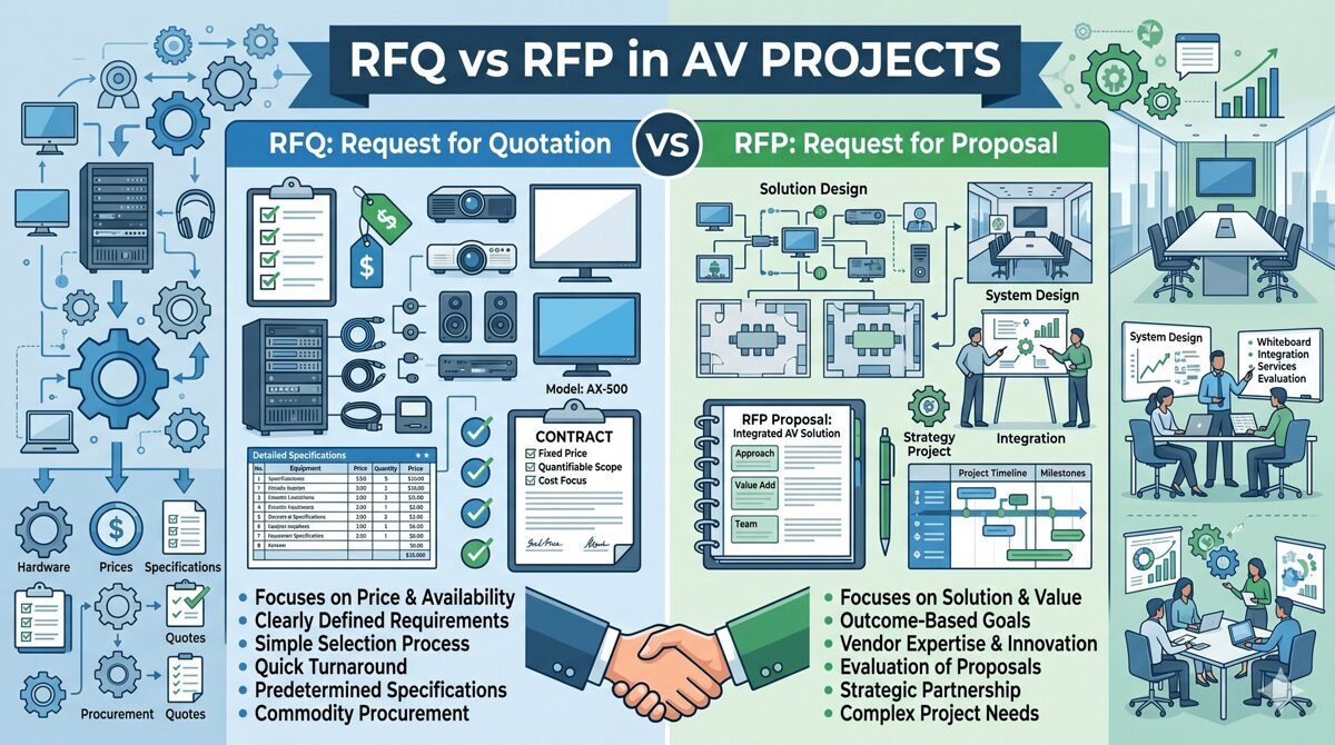
Understanding the RFQ vs RFP Difference: An Integrator's Perspective
The RFQ vs RFP difference creates two entirely different playing fields for AV integrators, each requiring distinct strategies, resources, and competitive approaches.
What RFQs Mean for Your Business
When you receive an RFQ, the client has already made every technical decision. An AV consultant or internal team has specified exact equipment, installation methods, cable types, and system architecture. Your quotation is essentially a bid to execute their predetermined design.
RFQ Characteristics
Documentation you'll receive:
Complete CAD drawings with equipment locations
Detailed bill of materials with part numbers
Comprehensive wiring diagrams and signal flow
Installation specifications and standards
Testing protocols and acceptance criteria
Fixed project timeline with milestones
Your competitive position:
Price is the primary (often 70-80%) evaluation factor
Qualifications matter but are secondary
Limited opportunity to differentiate through design
Profit margins compressed by competitive pressure
Execution capability more important than innovation
Resource requirements:
Estimating time: 8-20 hours typical
Design work: None required
Proposal length: 10-25 pages standard
Response period: 2-3 weeks typical
Win rate target: 20-30% realistic
What RFPs Mean for Your Business
When you receive an RFP, the client needs your professional expertise. They understand their operational goals but require design recommendations, technology selection, and implementation strategy from qualified integrators.
RFP Characteristics
Documentation you'll receive:
Functional requirements and use cases
Business objectives and strategic goals
Budget parameters (ranges, not fixed)
Evaluation criteria with multiple factors
Submission requirements for comprehensive proposals
Flexibility for vendor creativity and alternatives
Your competitive position:
Technical approach weighted 30-35% typically
Qualifications and experience 20-25%
Methodology and project management 15-20%
Price typically only 20-30% of evaluation
Innovation and differentiation highly valued
Resource requirements:
Proposal development time: 80-200 hours
Design work: Substantial—system architecture, drawings, integration diagrams
Proposal length: 50-150 pages comprehensive
Response period: 4-6 weeks typical
Win rate target: 40-60% achievable with strong technical approach
Critical Distinctions Table
Factor | RFQ Response | RFP Response |
Primary Focus | Price competitiveness | Technical solution quality |
Design Responsibility | None—execute client specs | Full—recommend optimal design |
Differentiation Strategy | Efficiency, service, qualifications | Innovation, expertise, methodology |
Time Investment | 8-20 hours | 80-200 hours |
Team Involvement | Estimating, PM | Design, engineering, PM, sales |
Profit Potential | 8-15% typical | 18-30% achievable |
Win Rate | 20-30% | 40-60% with good fit |
Presentation Required | Rare | Common for shortlist |
Price Pressure | Extreme | Moderate—value matters |
Best Practices for Responding to RFQs as an AV Integrator
Maximizing your RFQ win rate and profitability requires specific strategies focused on cost accuracy, response efficiency, and qualification differentiation.
Best Practice 1: Rapid Qualification Assessment
Before investing time, determine if the RFQ is worth pursuing:
Go/No-Go Criteria (Complete Within 30 Minutes)
Pursue if:
✓ Specifications align with your technical capabilities
✓ Equipment manufacturers match your partnerships and certifications
✓ Project size fits your bonding capacity and resource availability
✓ Geographic location within your service area
✓ Client has realistic budget (if indicated)
✓ Timeline feasible given current workload
✓ You have competitive advantage (relationships, local presence, specialized expertise)
Pass if:
✗ Specifications favor competitor's technology stack
✗ Project requires certifications you lack
✗ Geographic location creates unsustainable overhead
✗ Timeline impossible given current commitments
✗ Incumbent advantage insurmountable
✗ Profit margin potential below 10%
Decision rule: Only bid RFQs where you have legitimate win probability of 15%+ and acceptable profit potential.
Best Practice 2: Accurate and Efficient Cost Estimation
RFQ success hinges on pricing accuracy and competitive positioning.
Estimating Methodology
Equipment pricing strategies:
Leverage manufacturer volume discounts and dealer pricing
Use current pricing databases (updated weekly in June 2026)
Include freight, handling, and logistics costs
Factor in equipment lead times and potential backorder risks
Consider technology lifecycle position (avoid soon-obsolete equipment)
Labor estimation best practices:
Use historical data from similar projects (AI tools analyze this)
Account for site-specific factors (access restrictions, working hours, coordination)
Include realistic project management and supervision time
Factor in commissioning, testing, and documentation labor
Don't underestimate punch list and warranty service time
Risk and contingency:
Include 5-8% contingency for RFQ unknowns
Higher contingency (10-15%) for complex integration or challenging sites
Document assumptions in bid to protect against scope creep
Best Practice 3: Strategic Pricing Positioning
Understanding where to position your pricing improves win rates:
Competitive intelligence (June 2026 tools):
AI platforms like BidIntel predict competitor pricing (±8% accuracy)
Historical win/loss data analysis shows your competitive positioning
Market rate databases provide benchmark pricing by region
Pricing strategies:
Price to win: Target 15-20% below estimated competition if capacity allows
Price for profit: Add 10-15% premium if you have competitive advantages
Strategic loss leader: Consider low profit margins (5-8%) for key account entry
Walk-away pricing: Add 20%+ premium if project is marginal fit
Best Practice 4: Differentiate Beyond Price
Even in price-focused RFQs, emphasize your qualifications:
Differentiation elements:
Industry certifications (CTS, CTS-I, manufacturer credentials)
Relevant project experience with specific references
Local presence and service infrastructure
Financial stability and bonding capacity
Safety record and training programs
Warranty enhancements beyond minimum requirements
Project management methodology and communication protocols
Presentation matters:
Professional bid formatting and organization
Clear pricing tables with detailed breakdowns
Comprehensive qualifications package
Proactive risk mitigation statements
Schedule confidence with milestone clarity
Best Practices for Responding to RFPs as an AV Integrator
RFP responses offer greater opportunity for differentiation and profit margins but demand substantially more investment.
Best Practice 5: Early Engagement and Pre-RFP Positioning
The most successful integrators win RFPs before they're released through relationship building.
Pre-RFP Engagement Strategy
Intelligence gathering (3-6 months before RFP):
Identify potential projects through industry networks, construction reports, public notices
Connect with facility managers, technology directors, procurement teams
Offer educational workshops, technology demonstrations, site tours
Provide preliminary design concepts and budget guidance (no charge)
Establish trusted advisor status before procurement begins
Statistics: In June 2026, integrators who engage clients before RFP release achieve 55-70% win rates versus 15-25% for those responding cold.
Best Practice 6: Comprehensive Needs Assessment
When you receive an RFP, conduct thorough discovery:
Assessment Process
Attend pre-proposal conferences:
Ask insightful questions demonstrating expertise
Clarify ambiguities in requirements
Understand evaluation process and decision criteria
Identify key stakeholders and their priorities
Conduct detailed site surveys:
Document existing infrastructure comprehensively
Identify integration challenges and opportunities
Take photos and measurements for design accuracy
Engage on-site staff to understand workflow realities
Stakeholder interviews (if permitted):
Understand user requirements beyond RFP document
Identify pain points with current systems
Discover unstated needs and value opportunities
Build relationships with end users and technical staff
Best Practice 7: Design Excellence and Innovation
Your technical approach is typically the highest-weighted evaluation factor in RFPs.
Design Best Practices
System architecture:
Propose scalable solutions that accommodate future growth
Emphasize reliability through redundancy and quality components
Demonstrate integration expertise across technology platforms
Address lifecycle costs and total cost of ownership
Include technology roadmap for 5-7 year horizon
Innovation opportunities:
Recommend emerging technologies that provide competitive advantage
Propose AI-enhanced features (room analytics, predictive maintenance)
Suggest sustainability improvements (energy efficiency, green certifications)
Offer user experience enhancements beyond baseline requirements
Technical documentation:
Professional CAD drawings using industry-standard tools
Clear system diagrams and signal flow documentation
Detailed equipment specifications with rationale
Integration architecture showing all system interfaces
Testing and commissioning protocols
Best Practice 8: Compelling Proposal Development
Your proposal must sell your solution and your company.
Proposal Structure Best Practices
Executive summary (2-4 pages):
Demonstrate understanding of client objectives
Highlight key differentiators and value propositions
Summarize recommended solution at strategic level
Include compelling client-focused benefits
Technical approach (40-50% of proposal):
Detailed system design with drawings and diagrams
Equipment recommendations with selection rationale
Integration methodology and technical strategies
Testing and quality assurance approaches
Innovation elements and value engineering
Project methodology (15-20% of proposal):
Comprehensive project plan with timeline
Risk management strategies and mitigation plans
Communication protocols and reporting structure
Safety program and site coordination
Quality control procedures
Qualifications (15-20% of proposal):
Company overview and market position
Relevant project experience with detailed case studies
Team bios emphasizing credentials and experience
Certifications, partnerships, manufacturer relationships
References from similar successful projects
Cost proposal (10-15% of proposal):
Detailed line-item budget with transparency
Clear assumptions and exclusions
Payment schedule aligned with milestones
Value engineering options and alternatives
Warranty and service offerings
Best Practice 9: Presentation Excellence
Most RFP processes include presentations for shortlisted vendors.
Presentation Strategies
Preparation:
Rehearse with full team multiple times
Anticipate questions and prepare responses
Create compelling visual materials and demonstrations
Customize presentation to evaluation committee composition
Time presentation to respect stated limits (typically 30-60 minutes)
Delivery:
Lead with project team who will actually execute work
Demonstrate enthusiasm and commitment to client success
Address evaluation criteria explicitly
Show, don't just tell—use visuals, demos, mockups
Close with clear differentiation and value proposition
Post-presentation:
Submit clarifications promptly if requested
Provide additional references or case studies if needed
Maintain professional communication throughout evaluation
Be prepared for contract negotiation discussions
Strategic Positioning as an AV Integrator
Understanding the RFQ vs RFP difference helps you strategically position your business in the market.
Strategic Business Decisions
Choosing Your Competitive Focus
Volume-focused integrators (RFQ emphasis):
Build operational efficiency for cost competitiveness
Invest in estimating tools and process optimization
Maintain broad manufacturer relationships for pricing flexibility
Target standardized, repeatable project types
Accept lower margins (8-15%) with higher volume
Value-focused integrators (RFP emphasis):
Invest in design capabilities and engineering talent
Develop specialized vertical market expertise
Build consultative relationships with key clients
Target complex, custom projects with higher margins (18-30%)
Accept lower volume with higher profit per project
Hybrid approach (most common):
Pursue RFPs for strategic clients and complex projects
Bid RFQs for capacity management and market presence
Allocate resources based on profit potential and strategic value
Market Positioning Strategies
Geographic focus:
Local presence provides competitive advantage for RFQs (faster service, lower overhead)
Regional or national reach necessary for large RFP opportunities
Vertical specialization:
Healthcare, education, corporate, government, hospitality—each has unique procurement patterns
Specialization improves RFP win rates through demonstrable expertise
Vertical credentials and case studies differentiate from generalists
Technology specialization:
Unified communications, digital signage, control systems, video walls
Deep technical expertise commands premium pricing in RFPs
Manufacturer certifications validate capabilities
AI and Technology Transforming AV Proposals in June 2026
As of mid-2026, artificial intelligence and automation technologies are revolutionizing how AV integrators respond to both RFQs and RFPs.
AI-Powered Estimating and Proposal Tools
Cost Estimation Automation
Leading platforms available June 2026:
Estimate IQ AV:
Analyzes RFQ documents using natural language processing
Extracts equipment lists and labor requirements automatically
Suggests competitive pricing based on historical win/loss data
Predicts competitor pricing with 85-90% accuracy
Generates line-item quotations in 2-3 hours versus 8-12 hours manually
Pricing Optimizer Pro:
Machine learning analyzes your historical project data
Recommends optimal pricing based on win probability targets
Accounts for current capacity, strategic priorities, competitor intelligence
Provides confidence intervals on cost estimates
Reduces estimating errors by 40-60%
RFP Response Automation
Proposal AI Suite:
Natural language generation creates proposal sections from templates
Learns from your winning proposals to replicate success patterns
Suggests technical approaches based on requirements analysis
Auto-generates equipment specifications and system diagrams
Reduces proposal development time by 30-50%
Design Assist Pro:
AI-powered system design recommendations
Equipment compatibility checking across manufacturers
Code compliance verification (NFPA, NEC, ADA)
3D visualization generation for client presentations
Integration architecture optimization
Competitive Intelligence and Market Analysis
BidIntel Platform:
Tracks competitor bidding patterns and win rates
Predicts which competitors likely to bid on solicitations
Analyzes pricing strategies and competitive positioning
Identifies emerging market opportunities and trends
Subscription service available in June 2026 ($2,500-$8,000/year)
Virtual Collaboration and Presentation Tools
Proposal VR:
Virtual reality system demonstrations during presentations
Interactive walkthroughs of proposed AV installations
Remote site surveys using VR technology
Immersive presentations differentiating from competitors
Digital Twin Technology:
Create digital replicas of proposed systems
Simulate performance under various scenarios
Demonstrate maintenance procedures virtually
Provide training environments before installation
Common Mistakes and How to Avoid Them
Learning from typical errors improves your win rates and profitability.
RFQ Response Mistakes
Mistake 1: Bidding Every RFQ Problem: Wastes time on unwinnable projects, dilutes focus Solution: Implement disciplined go/no-go criteria, target 15%+ win probability
Mistake 2: Incomplete or Unclear Pricing Problem: Client uncertainty leads to disqualification or questions Solution: Provide detailed line-item pricing, clear assumptions, comprehensive scope documentation
Mistake 3: Ignoring Qualifications Problem: Lowest price doesn't always win—qualifications break ties Solution: Include strong qualifications package, relevant references, certifications
Mistake 4: Missing Submission Requirements Problem: Automatic disqualification for non-compliance Solution: Create submission checklist, review RFQ requirements multiple times
RFP Response Mistakes
Mistake 5: Generic, Templated Proposals Problem: Fails to differentiate, doesn't address client-specific needs Solution: Customize every section, reference client context, demonstrate understanding
Mistake 6: Overengineering Solutions Problem: Exceeds budget, creates perception of unnecessary complexity Solution: Design to requirements, provide value engineering alternatives, respect budget guidance
Mistake 7: Weak Executive Summary Problem: Evaluators may only read summary—must compel them Solution: Invest heavily in executive summary, emphasize client benefits, differentiate clearly
Mistake 8: No Follow-Up or Presentation Prep Problem: Loses momentum, poor presentation performance Solution: Maintain communication, prepare thoroughly for presentations, rehearse extensively
Strategic Mistakes
Mistake 9: Wrong Market Positioning Problem: Competing on price in value markets or vice versa Solution: Clarify your market position, target appropriate procurement types
Mistake 10: Inadequate Resource Allocation Problem: Spreading too thin across too many proposals Solution: Be selective, focus resources on best-fit opportunities, track win rates by project type
Frequently Asked Questions
What is the RFQ vs RFP difference from an integrator's perspective?
The RFQ vs RFP difference fundamentally changes your response strategy and profit potential. RFQs request pricing for complete client-provided specifications—you compete primarily on cost and execution capability with 8-15% typical margins and 20-30% win rates. RFPs solicit comprehensive solutions including design recommendations—you compete on technical expertise, innovation, and value with 18-30% potential margins and 40-60% win rates when well-positioned. RFQ responses require 8-20 hours; RFP proposals demand 80-200 hours investment.
How do I decide whether to bid an RFQ or RFP?
For RFQs, apply go/no-go criteria: only bid if you have 15%+ win probability (competitive pricing, relevant experience, no insurmountable disadvantages) and acceptable profit potential (10%+ margin). For RFPs, pursue if: (1) project aligns with your technical capabilities and vertical expertise, (2) you have or can build client relationships, (3) timeline allows quality proposal development (80-200 hours), and (4) budget supports profitable execution. Track your win rates by type—stop bidding categories where you consistently lose.
What AI tools are available in June 2026 to help with proposals?
Leading AI platforms in June 2026 include: EstimateIQ AV (automated cost estimation from RFQ documents, 85-90% pricing accuracy), ProposalAI Suite (natural language generation for proposal sections, 30-50% time savings), DesignAssist Pro (AI-powered system design recommendations and CAD generation), BidIntel Platform (competitor intelligence and market analysis), and Proposal VR (virtual reality presentations). These tools cost $1,500-$8,000 annually but deliver ROI through increased win rates (10-15% improvement) and reduced labor costs (30-60 hours saved per RFP).
Should I specialize in RFQs or RFPs strategically?
Most successful integrators pursue a hybrid approach but with clear strategic priorities. Volume-focused businesses emphasize RFQs through operational efficiency, competitive pricing, and process optimization—accepting 8-15% margins with higher project volume. Value-focused businesses emphasize RFPs through design capabilities, vertical specialization, and consultative relationships—targeting 18-30% margins with lower volume. Your choice depends on company size, technical capabilities, market position, and growth objectives. Track profitability by procurement type to optimize your mix.
How can I improve my RFP win rates?
Improve RFP win rates through: (1) Pre-RFP engagement—70% of awards go to vendors who built relationships before solicitation (attend industry events, offer educational sessions, provide preliminary guidance), (2) Design excellence—invest in professional CAD tools, hire experienced designers, showcase innovation, (3) Proposal quality—customize every section, create compelling executive summaries, include relevant case studies, (4) Presentation skills—rehearse extensively, demonstrate with actual team, address evaluation criteria explicitly, (5) Strategic targeting—only pursue RFPs matching your strengths and market position.
What profit margins should I target for RFQs versus RFPs?
Target profit margins differ significantly: RFQs typically yield 8-15% margins due to price-focused competition and limited differentiation opportunities—efficiency and volume drive profitability. RFPs enable 18-30% margins through value-added services, design expertise, and multi-factor evaluation—technical differentiation commands premium pricing. Track your actual margins by procurement type and client category. Walk away from RFQs yielding below 10% unless strategically important for account entry or market presence. For RFPs, insufficient margins (below 18%) suggest inadequate differentiation or inappropriate targeting.
How much time should I invest in RFQ versus RFP responses?
Time investment should match opportunity value and win probability: RFQ responses require 8-20 hours typical (estimating, pricing, qualifications package, submission)—limit investment since price dominates evaluation. RFP proposals demand 80-200 hours (discovery, design, proposal writing, presentations)—substantial investment justified by higher margins and win rates. Calculate ROI: if RFP win probability is 50%, project value is $500K, and margin is 25% ($125K profit), then 150-hour investment ($15K-$22K cost) yields strong return. Stop pursuing opportunities where time investment exceeds profit potential × win probability.
Conclusion
Mastering the RFQ vs RFP difference is fundamental to building a successful, profitable AV integration business in 2026 and beyond. These aren't simply different document formats—they represent entirely different competitive landscapes, business opportunities, and strategic positioning choices that shape your company's trajectory, profit margins, and market reputation.
RFQs offer volume opportunities with efficient, price-focused competition where operational excellence, accurate cost estimation, and execution capability drive success. While profit margins are compressed (8-15% typical), disciplined go/no-go criteria, technology-enhanced estimating, and strategic pricing enable sustainable profitability through volume. Win rates of 20-30% are realistic when targeting appropriate opportunities and competing effectively on price and qualifications.
RFPs provide value opportunities where your design expertise, technical innovation, and consultative approach command premium pricing (18-30% margins achievable) and higher win rates (40-60% with strong positioning). Success requires substantial investment in proposal development (80-200 hours), but multi-factor evaluation rewards technical differentiation over lowest price. Pre-RFP engagement, comprehensive needs assessment, design excellence, and compelling proposals separate winners from participants.
In June 2026, AI-powered tools are revolutionizing both RFQ and RFP responses through automated estimation (reducing time 40-60%), intelligent design assistance, competitive intelligence, and virtual presentations. Forward-thinking integrators investing in these technologies ($5K-$15K annually) achieve 10-15% higher win rates and 30-50% faster proposal development while maintaining quality and differentiation.
The most successful AV integrators don't treat all procurement opportunities identically—they strategically position their businesses, allocate resources based on profit potential and win probability, and continuously refine their approaches based on tracked performance metrics. Whether you emphasize volume-focused RFQ efficiency, value-focused RFP expertise, or a strategic hybrid, understanding and exploiting the RFQ vs RFP difference positions your company for sustainable profitability, competitive advantage, and long-term success in an increasingly sophisticated and competitive audiovisual market.
Apply these best practices, leverage available AI tools, track your win rates and margins by procurement type, and continuously optimize your approach. Your mastery of the RFQ vs RFP difference will directly determine your business performance in the years ahead.
How Access Control Systems Work: Step-by-Step Guide
Understanding how access control systems function is essential for AV integrators, security consultants, and system designers who specify and implement physical security infrastructure in 2026. Access controls systems regulate entry to buildings, rooms, and restricted areas through electronic authentication rather than traditional mechanical keys, creating secure, auditable, and manageable environments. Knowing how access controls systems operate—from credential presentation to door unlocking to event logging—enables professionals to design effective solutions, troubleshoot issues, and optimize security performance for clients. At its core, an access control system validates user identity, checks authorization permissions, controls locking hardware, and records all events in a continuous cycle that occurs thousands of times daily across facilities.
This comprehensive guide breaks down the complete access control workflow, explaining each component's role, the communication between system elements, and how authentication decisions happen in milliseconds. Whether you're designing your first access control installation or optimizing enterprise deployments, understanding these fundamental processes ensures successful implementations.
Key Takeaways
✅ Access controls systems authenticate users, verify permissions, control locks, and log events in coordinated processes
✅ The complete access control cycle involves credentials, readers, controllers, locking hardware, and management software working together
✅ Modern systems process authentication in 200-500 milliseconds from credential presentation to door unlocking
✅ Controllers store local databases enabling operation during network outages or server failures
✅ Cloud-based and on-premise systems use identical door hardware but differ in management architecture
✅ AI-powered features enhance security through behavioral analytics, predictive maintenance, and automated threat detection
✅ Understanding the complete workflow enables better system design, troubleshooting, and performance optimization
What Is an Access Control System?
An access control system is an integrated electronic security solution that manages and monitors who can enter specific areas within a facility, when they can access them, and what actions they can perform. These systems replace traditional lock-and-key mechanisms with intelligent authentication, authorization, and audit capabilities.
Core System Components
Access controls systems consist of interconnected hardware and software elements:
1. Credentials
Credentials are digital identifiers proving user identity:
Proximity Cards: Basic RFID cards operating at 125 kHz for simple access Smart Cards: Advanced contactless credentials with encryption (13.56 MHz like DESFire) Mobile Credentials: Smartphone-based digital credentials using Bluetooth Low Energy or NFC Biometric Data: Fingerprint, facial recognition, iris patterns, or palm vein characteristics PIN Codes: Numeric codes entered via keypads for knowledge-based authentication
2. Readers
Readers capture credential information at entry points:
Card Readers: RFID readers detecting proximity cards or smart cards within 2-6 inches Biometric Readers: Fingerprint scanners, facial recognition cameras, iris scanners capturing biological characteristics Keypads: Numeric pads accepting PIN codes for entry Mobile Readers: Bluetooth or NFC readers communicating with smartphones Multi-Technology Readers: Supporting multiple credential types simultaneously
3. Controllers
Access control panels (controllers) are the system's intelligence:
Processing Unit: Makes authentication decisions based on programmed rules Memory Storage: Stores user databases, access permissions, schedules, and event logs locally Communication Interface: Connects to management software via TCP/IP, RS-485, or wireless protocols I/O Ports: Controls door locks, monitors door status sensors, request-to-exit devices, and alarm inputs Offline Capability: Continues operating during network or server failures using cached data
4. Locking Hardware
Electric locks physically secure doors:
Electromagnetic Locks (Mag Locks): Powerful magnets providing 600-1,200 pounds holding force, fail-safe (unlock when power lost) Electric Strikes: Replace traditional door strikes, releasing to allow latch bolt passage, configurable fail-safe or fail-secure Electrified Mortise Locks: Complete lock mechanisms with electronic control, highest security Wireless Locks: Battery-powered locks with wireless communication, ideal for retrofit applications
5. Management Software
Access control software provides administrative interface:
User Management: Creating users, assigning credentials, defining access permissions Access Policies: Configuring role-based access, time schedules, zone restrictions Real-Time Monitoring: Viewing live access events, door status, alarm conditions Reporting: Generating audit trails, compliance reports, security analytics Integration: Connecting with video surveillance, alarm systems, building automation
System Architecture Types
Access controls systems deploy in different architectural models:
Standalone Systems: Single controller with local programming, suitable for 1-5 doors Networked Systems: Multiple controllers connected via LAN/WAN with centralized management software Cloud-Based Systems: Controllers communicating with cloud-hosted software via internet Hybrid Systems: Local controllers with offline capabilities but cloud management interface
Why Are Access Control Systems Important?
Understanding access controls systems importance helps AV integrators communicate value to clients and justify investments in sophisticated security infrastructure.
Physical Security and Asset Protection
Access controls systems create layered security perimeters:
Unauthorized Access Prevention: Only authorized personnel enter restricted areas like data centers, laboratories, executive offices, and inventory storage
Time-Based Access: Employees access facilities only during assigned shifts, preventing after-hours entry without authorization
Zone Segmentation: Different areas require different clearance levels, containing threats to specific zones
Forced Entry Detection: Door forced open and door held open alarms notify security immediately
Regulatory Compliance and Audit Requirements
Many industries mandate access control for compliance:
HIPAA (healthcare) requires protecting patient information areas PCI-DSS (payment processing) mandates physical security for cardholder data environments SOX (financial reporting) demands controls over financial systems access ITAR (defense) requires strict control of technical data and facilities
Audit trails from access controls systems document who accessed protected resources, when, and for how long—essential for compliance demonstrations.
Operational Efficiency
Access controls systems improve facility operations:
Eliminated Key Management: No physical keys to issue, track, collect, or rekey Automated Scheduling: Time-based access permissions for contractors, cleaning crews, part-time staff Remote Administration: Grant or revoke access instantly from anywhere Reduced Security Personnel: Automated monitoring reduces staffing needs
Safety and Emergency Response
Access controls systems support life safety:
Emergency Egress: Fail-safe locks unlock automatically during fire alarms ensuring safe escape Lockdown Capabilities: Secure facilities during active threats Evacuation Tracking: Identify who evacuated versus remaining inside First Responder Access: Provide emergency services controlled entry
Business Intelligence
Modern systems provide valuable data:
Occupancy Analytics: Real-time facility occupancy for space utilization Traffic Patterns: Understanding peak usage times for staffing and resource allocation Behavioral Insights: Identifying unusual patterns indicating security concerns Integration Data: Coordinating access events with video surveillance and other systems
How Access Control Systems Work: Step-by-Step Process
Understanding the complete access control workflow enables system designers to optimize performance, troubleshoot issues, and explain functionality to clients.
The Complete Access Control Cycle
Step 1: Credential Presentation
The process begins when a user approaches a secured door:
Physical Action: User presents credential to reader—tapping proximity card, holding smartphone near Bluetooth reader, or looking at facial recognition camera
Reader Activation: Reader powers on (if passive), activates scanning, and prepares to capture credential data
Data Capture: Reader extracts identifier from credential—card number from RFID chip, biometric template from fingerprint, UUID from smartphone
Time: 50-200 milliseconds depending on credential type and reader technology
Step 2: Data Transmission to Controller
Reader sends captured data to controller:
Communication Protocol: Data transmitted via Wiegand (traditional hardwired), OSDP (encrypted communication), TCP/IP (networked readers), or wireless protocols
Data Format: Includes credential identifier, reader location, timestamp, and data type (card, biometric, PIN)
Encryption: Modern systems use encrypted transmission preventing credential interception
Time: 10-50 milliseconds depending on communication method and distance
Step 3: Controller Authentication
Controller processes the authentication request:
Database Query: Controller searches local user database for matching credential identifier
User Validation: Confirms credential is active, not expired, and assigned to valid user
Permission Check: Verifies user has access permission for this specific reader/door
Schedule Verification: Confirms current time falls within user's allowed access schedule (e.g., Monday-Friday 8am-6pm)
Zone Logic: Checks anti-passback rules, occupancy limits, or dual-authentication requirements if configured
Threat Level: Evaluates any active lockdowns or security conditions affecting access
Time: 50-150 milliseconds for database lookup and rule evaluation
Step 4: Authorization Decision
Controller makes final access decision:
Granted: All conditions satisfied—user, permission, schedule, zone rules Denied: One or more conditions failed—invalid credential, no permission, wrong time, violated rules
Communication: Controller prepares response to reader and locking hardware
Time: 5-10 milliseconds for decision processing
Step 5: Lock Control
Controller activates locking hardware if access granted:
Relay Activation: Controller energizes output relay connected to door lock
Lock Response:
Electromagnetic lock: Magnet releases, allowing door to open
Electric strike: Strike retracts, freeing door latch bolt
Electrified mortise: Lock mechanism disengages
Duration: Lock remains unlocked for programmed door unlock time (typically 3-10 seconds)
Re-Lock: After unlock period or door closes (REX sensor detection), lock re-secures automatically
Time: 10-50 milliseconds for relay activation, plus mechanical response time of lock (20-100 milliseconds)
Step 6: User Feedback
System provides feedback to user:
Visual Indicators: LED on reader flashes green (granted) or red (denied)
Audible Feedback: Beep patterns indicating success or failure
Display Messages: Some readers show text messages ("Access Granted," "Invalid Card," "Access Denied")
Lock Sounds: Distinctive sounds from mag lock release or strike retraction confirm access
Time: Simultaneous with lock control
Step 7: Event Logging
Controller records the access event:
Event Data: Captures user identity, credential used, reader location, timestamp, granted/denied status, door open/close time
Local Storage: Saves event to controller memory (typically stores 10,000-100,000 events)
Server Upload: Transmits event to management software for permanent storage (real-time for networked systems, batch for periodic sync)
Time: 5-20 milliseconds for local logging, variable for server upload
Step 8: Physical Door Opening
User completes the process:
Door Opening: User pushes/pulls door open during unlock period
Door Sensor: Magnetic contact detects door opened, reports to controller
REX Detection: Request-to-exit sensor detects person passing through doorway
Door Close: User allows door to close, sensor detects closure, lock re-secures
Monitoring: Controller monitors door status for forced open or door held open violations
Complete Cycle Timing
Total time from credential presentation to door unlock: 200-500 milliseconds
Card-based access: 200-300 milliseconds (fastest)
Mobile credentials: 250-400 milliseconds (includes Bluetooth handshake)
Biometric authentication: 300-500 milliseconds (includes template matching)
Multi-factor authentication: 400-800 milliseconds (card + PIN, etc.)
What Happens During Network or Power Failures?
Network Outage
Access control continues normally because:
Local Database: Controllers store complete user database locally Autonomous Operation: Controllers make authentication decisions independently Event Buffering: Events stored in controller memory, uploaded when connectivity restores Limitations: Cannot modify permissions remotely until network returns
Power Failure
Backup systems maintain operation:
Controller Battery: Internal battery powers controller for 4-24 hours Lock Behavior:
Fail-safe locks (mag locks) unlock when power lost (life safety requirement)
Fail-secure locks (some strikes) remain locked during power loss UPS Systems: Uninterruptible power supplies protect complete systems in critical facilities
Cloud-Based vs On-Premise Access Control
The system architecture affects where authentication processing and data storage occur, but the door-level workflow remains largely identical.
On-Premise (Traditional) Systems
Architecture:
Management software runs on local servers within facility
Controllers communicate with servers via LAN
All data stored on customer-owned infrastructure
Workflow:
Controllers sync user databases from local servers
Authentication occurs at controller using cached data
Events upload to local servers for storage
Administrators access system from workstations on corporate network
Advantages: Complete data control, network isolation possible, no internet dependency Disadvantages: Requires server infrastructure, IT management, limited remote access
Cloud-Based Systems
Architecture:
Management software hosted on vendor cloud servers
Controllers communicate with cloud via internet
Data stored in vendor-managed infrastructure
Workflow:
Controllers sync user databases from cloud platform
Authentication occurs at controller using cached data (identical to on-premise)
Events upload to cloud servers immediately or during periodic sync
Administrators access system via web browser or mobile app from anywhere
Advantages: No local servers, remote management, automatic updates, unlimited scalability Disadvantages: Internet dependency for administration, subscription costs, vendor data control
Door-Level Process Comparison
Process Step | On-Premise | Cloud-Based | Difference |
Credential Presentation | Identical | Identical | None |
Reader to Controller | Identical | Identical | None |
Authentication | Local database | Local database | None |
Lock Control | Identical | Identical | None |
Event Logging | Local first | Local first | None |
Server Upload | LAN to local server | Internet to cloud | Network path |
Administration | On-site/VPN | Web/mobile anywhere | Access method |
Key Insight: The door hardware, readers, and authentication process function identically—architectural differences affect only management and administration, not real-time access control. |
Future Trends in Access Control Systems
Artificial intelligence, machine learning, and emerging technologies transform how access controls systems operate in June 2026 and beyond.
AI-Powered Authentication
Machine learning enhances access control decisions:
Behavioral Analytics
AI algorithms learn normal behavior patterns:
Pattern Recognition: Systems analyze months of access data establishing baselines—typical arrival times, frequently used doors, common pathways through facilities
Anomaly Detection: Unusual behavior triggers alerts—accessing restricted areas, entering at odd hours, rapid entries at multiple distant doors
Dynamic Risk Scoring: Each access attempt receives risk score based on multiple factors, triggering additional authentication for high-risk scenarios
Insider Threat Detection: Identifying concerning patterns suggesting malicious intent or compromised credentials
Intelligent Access Policies
AI optimizes access permissions:
Automated Provisioning: Natural language processing interprets access requests implementing appropriate permissions automatically
Context-Aware Access: Permissions adjust based on location, time, threat level, and other contextual factors
Predictive Security: Forecasting potential security incidents based on patterns and implementing preventive measures
Advanced Biometric Technologies
Next-generation biometrics improve authentication:
3D Facial Recognition: Detecting faces at walking speed without stopping, working with masks and glasses
Multi-Modal Biometrics: Combining facial recognition with gait analysis or other characteristics for enhanced accuracy
Liveness Detection: AI-powered systems preventing spoofing attempts using photos, videos, or masks
Continuous Authentication: Ongoing identity verification throughout facility presence rather than single entry-point authentication
Touchless and Frictionless Access
Convenience-focused technologies eliminate physical interaction:
Long-Range Bluetooth: Mobile credentials detected 50-300 feet away, doors unlocking automatically as users approach
Facial Recognition at Distance: Identifying users from 10-30 feet enabling walking-speed authentication
Voice Biometrics: Speaker verification for hands-free authentication integrated with intercom systems
Gesture Recognition: Hand gestures triggering access in specialized environments
Predictive Maintenance
AI algorithms prevent equipment failures:
Performance Monitoring: Analyzing reader error rates, lock operation consistency, controller communication patterns
Failure Prediction: Identifying components likely to fail 1-4 weeks before occurrence
Automated Service Requests: Generating maintenance tickets automatically when issues detected
Optimization Recommendations: Suggesting configuration improvements based on usage patterns
Integration with Smart Buildings
Access controls systems becoming central hub for building operations:
Occupancy-Based Automation: HVAC, lighting, and elevator control responding to access events
Space Utilization Analytics: Monitoring which areas are used, when, and by whom for optimization
Energy Management: Automatically adjusting building systems based on occupancy detected through access control
Workplace Experience: Personalizing environments based on user preferences detected via credential
How XTEN-AV Helps You Design Complete Access Control Systems Faster
For AV integrators and security system designers, understanding how access controls systems work enables better design—and XTEN-AV accelerates the complete process from concept to installation.
Workflow-Based Design Tools
XTEN-AV supports the complete access control workflow:
Component Selection: Choose appropriate credentials, readers, controllers, and locks based on security requirements and authentication workflow
Reader Placement: Position readers at optimal locations considering user approach paths, credential type, and read range
Controller Configuration: Define which readers connect to which controllers, calculate input/output requirements
Network Design: Plan communication paths from readers to controllers to servers or cloud
Wiring Automation: Calculate cable runs, voltage drop, and generate wire schedules automatically
Timing and Performance Analysis
Optimize system responsiveness:
Latency Calculation: Estimate authentication timing based on credential type, communication method, and controller performance
Bandwidth Analysis: Ensure network capacity handles event traffic from all controllers
Load Balancing: Distribute doors across controllers preventing bottlenecks
Failover Planning: Design redundant paths ensuring continued operation during component failures
Integration Workflow Design
Plan coordinated system operations:
Video Surveillance: Map access events to camera triggers for event-based recording
Alarm Systems: Coordinate access zones with intrusion detection areas
Building Automation: Define occupancy-based control rules for HVAC and lighting
Visitor Management: Integrate temporary credential issuance with access control
Documentation for Operations
Generate materials explaining system workflow:
Process Diagrams: Visual flowcharts showing authentication process step-by-step
Troubleshooting Guides: Decision trees for diagnosing access failures at each process step
User Training: Documentation explaining how to present credentials and interpret feedback
Administrator Guides: Procedures for managing users, configuring permissions, reviewing audit logs
Testing and Commissioning Plans
Verify complete workflow functionality:
Test Sequences: Systematic testing of each authentication step—credential read, controller processing, lock activation, event logging
Timing Verification: Measure actual authentication speed confirming performance requirements
Failure Scenarios: Test behavior during network outages, power failures, invalid credentials
Integration Testing: Verify coordinated operation with video, alarms, and other systems
By understanding the complete access control workflow and using purpose-built design tools, AV integrators deliver optimized systems that perform reliably and meet client expectations.

Frequently Asked Questions
How fast should access control authentication happen?
Well-designed access controls systems complete the entire authentication cycle from credential presentation to door unlock within 200-500 milliseconds. Card-based access typically achieves 200-300 milliseconds, mobile credentials require 250-400 milliseconds including Bluetooth handshake, and biometric authentication takes 300-500 milliseconds for template matching and verification. Multi-factor authentication combining credential types extends timing to 400-800 milliseconds. Users perceive systems as "instant" when authentication completes under 500 milliseconds, while delays exceeding 1 second create noticeable frustration. Factors affecting speed include reader technology (contactless faster than insert), controller processing power, communication protocols (Wiegand fastest, encrypted OSDP slightly slower), network latency for cloud systems, and database size (larger databases require longer searches). System designers should specify performance requirements and test actual timing during commissioning.
What happens if the access control controller loses power?
When controllers lose power, behavior depends on backup systems and lock configuration. Modern controllers include internal batteries providing 4-24 hours of continued operation during outages, maintaining normal authentication and access control functionality. However, locking hardware behaves according to fail-safe or fail-secure configuration: electromagnetic locks (mag locks) always fail-safe, unlocking immediately when power lost to ensure life safety and fire code compliance; electric strikes can be configured fail-safe (unlock during power loss) or fail-secure (remain locked), depending on security versus safety priorities. Critical facilities deploy UPS systems providing clean power during outages and time for graceful shutdown or generator activation. Best practice includes testing backup power quarterly, maintaining batteries according to manufacturer specifications, and configuring locks appropriately for each door's security level and life safety requirements. High-security areas may use fail-secure locks with battery backup ensuring continued security during outages.
Can someone unlock doors if they hack the access control network?
Network security for access controls systems requires multiple protective layers. While theoretical vulnerabilities exist, properly configured systems resist attacks through several mechanisms: encrypted communication between controllers and servers prevents credential interception; authentication requirements for administrative access prevent unauthorized configuration changes; network segmentation isolates access control networks from general corporate networks reducing attack surfaces; local authentication at controllers means network access alone doesn't grant physical entry—attackers would need valid credentials not just network access; and audit logging records all system access and configuration changes enabling detection of unauthorized activity. Best practices include implementing VLANs dedicated to physical security systems, requiring multi-factor authentication for administrative access, using VPN for remote management, keeping firmware updated with security patches, and conducting regular security audits. Cloud-based systems benefit from professional security teams monitoring infrastructure continuously. While no system is perfectly secure, access controls systems from reputable manufacturers incorporate substantial security features when properly implemented.
How do access control systems handle visitors and temporary access?
Access controls systems support temporary access through several mechanisms integrated with visitor management. Traditional approaches issue temporary proximity cards or key fobs valid for specific timeframes (hours or days), which visitors return upon departure. Modern systems increasingly use mobile credentials sent via email or SMS, where visitors receive digital credentials on smartphones that automatically expire after visit completion. PIN codes assigned temporarily provide keypad-based access without physical credentials. Advanced implementations integrate dedicated visitor management systems that pre-register guests, perform background checks if required, capture photos, print badges, and automatically provision temporary access permissions for designated areas and timeframes. The access control workflow for visitors mirrors employee access—presenting credential, reader capture, controller authentication, permission verification—but with additional restrictions including time limits (credential expires automatically), area restrictions (access only to meeting rooms, not secure areas), escort requirements (some implementations require employee presence), and automated revocation (credentials deactivate immediately when visitor checks out). This provides security without operational burden of manually managing temporary access.
What's the difference between access granted and door forced open events?
Access controls systems distinguish between authorized and unauthorized door openings through event types captured during monitoring. An access granted event occurs when: user presents valid credential, controller authenticates and authorizes access, controller unlocks door for programmed duration (typically 3-10 seconds), user opens door during unlock period, door sensor detects opening, and controller logs legitimate entry event. A door forced open event (also called forced entry) occurs when: door opens without valid credential presentation, door sensor detects opening while door should be secured, controller immediately triggers alarm condition, and security team receives alert for investigation. This indicates potential security breach—unauthorized entry, door propped open, or hardware malfunction. Additional related events include door held open (door remains open beyond acceptable time after authorized access, suggesting someone prevented door from closing) and REX activated (person exited through request-to-exit device without using credential for entry, which may indicate tailgating). Understanding these distinctions helps security teams respond appropriately—access granted events are normal operations, while forced open events demand immediate investigation.
How do biometric access control systems work differently than card systems?
Biometric access control follows the same fundamental workflow as card-based systems but with critical differences in credential capture and authentication. The process includes: enrollment phase where users register biometric characteristics (fingerprint, facial features, iris patterns) converted into mathematical biometric templates stored in system database; authentication phase where users present biometric to reader (place finger on scanner, look at camera), reader captures biometric and creates template from presented sample, controller compares captured template against enrolled templates using matching algorithms, and system calculates match score determining if presented biometric sufficiently matches enrolled template (typically 95%+ threshold). Key differences from card systems include: credential cannot be lost, stolen, or shared (inherent to person); false acceptance and false rejection rates require balancing (stricter matching reduces false acceptance but increases false rejection); environmental factors affect performance (dirty fingers, lighting conditions, aging); privacy concerns require careful data handling (some jurisdictions regulate biometric data); and processing time slightly longer due to template matching complexity (300-500 milliseconds versus 200-300 for cards). Modern biometric readers incorporate liveness detection preventing spoofing with photographs or fake fingers, enhancing security beyond traditional card systems.
Do cloud-based access control systems authenticate slower than on-premise systems?
Authentication speed for cloud-based access control matches on-premise systems during normal operations because authentication processing occurs locally at controllers for both architectures. The workflow comparison shows: both cloud and on-premise controllers cache complete user databases locally; both perform credential validation, permission checks, and schedule verification using local data without server communication; both unlock doors in identical timeframes (200-500 milliseconds); and both store events locally before uploading to servers/cloud. The only timing difference occurs during database synchronization—when administrators add new users or modify permissions, cloud systems may take slightly longer (seconds to minutes) to propagate changes to controllers versus immediate synchronization on local networks. However, this synchronization delay doesn't affect authentication speed for existing users. The misconception about cloud slowness stems from confusing administrative tasks (performed remotely via internet) with real-time authentication (performed locally). Both architectures provide equivalent door-level performance. Cloud systems may actually perform better during server failures because cloud vendors maintain redundant infrastructure, while on-premise servers require customer-implemented redundancy for similar reliability.
Conclusion
Understanding how access controls systems work—from the millisecond-level authentication process to the interaction between credentials, readers, controllers, locks, and management software—empowers AV integrators, security consultants, and system designers to deliver optimized solutions that perform reliably and meet client expectations. The complete access control workflow demonstrates sophisticated coordination between multiple system elements occurring thousands of times daily across facilities, typically within 200-500 milliseconds from credential presentation to door unlock.
The fundamental process remains consistent regardless of system architecture: users present credentials to readers, which transmit data to controllers that authenticate against local databases, verify permissions and schedules, control locking hardware, provide user feedback, and log events for audit purposes. Whether deploying cloud-based or on-premise systems, this door-level workflow operates identically—architectural differences affect only management and administration approaches, not real-time access control performance.
As artificial intelligence, biometric technologies, and smart building integration continue advancing in June 2026 and beyond, access controls systems evolve from simple entry management to sophisticated platforms providing behavioral analytics, predictive security, automated responses, and comprehensive building intelligence. Understanding these fundamentals enables designing systems that leverage emerging capabilities while maintaining the reliable, secure, auditable access control that protects people, assets, and information.
For professionals designing and implementing these systems, tools like XTEN-AV accelerate the complete process—from component selection through workflow optimization to documentation generation—enabling efficient delivery of sophisticated access control solutions. By combining deep understanding of system operation with purpose-built design tools, AV integrators deliver superior outcomes that enhance security, improve operations, and provide long-term value for clients across diverse facility types and security requirements.
Take Action: Apply this workflow knowledge to your next access control design, optimize component selection based on performance requirements, verify timing during commissioning, and educate clients about system operation ensuring they understand and maximize their security investment.
Ceiling Speakers for Surround Sound in Open-Concept Homes: Challenges and Solutions
Open-concept living spaces present unique acoustic challenges for home theater installations, particularly when implementing ceiling mount surround sound speakers in environments where traditional wall placement isn't feasible. As modern architecture increasingly favors open floor plans that combine living rooms, kitchens, and dining areas into expansive connected spaces, AV integrators face complex decisions about speaker positioning, acoustic treatment, and system calibration to deliver immersive audio experiences. The importance of choosing the best ceiling mount surround sound speakers extends beyond simple product selection—it requires understanding acoustic principles, architectural constraints, and client lifestyle patterns to create surround sound systems that perform effectively in acoustically challenging environments.
Open-concept homes lack the defined boundaries and reflective surfaces that help contain and direct sound in traditional enclosed rooms, creating issues with sound localization, dialogue intelligibility, and bass response. Ceiling speakers become the practical solution when walls are occupied by windows, artwork, or architectural features, or when aesthetic preferences demand minimal visible equipment. However, successful implementation requires addressing specific challenges: vertical sound delivery creating unnatural listening experiences, ceiling height variations affecting coverage, and hard surface materials (wood, tile, glass) causing excessive acoustic reflections that muddy audio clarity.
This comprehensive guide examines the technical challenges inherent in ceiling-mounted surround sound for open-concept spaces and provides practical solutions that AV professionals can implement to deliver superior audio performance despite architectural limitations.
Key Takeaways
Open-concept spaces create acoustic challenges including excessive reverberation (RT60 often 0.8-1.2+ seconds), weak bass response, and poor sound localization
Ceiling mount surround sound speakers require strategic positioning accounting for listening zones, ceiling height, and architectural features affecting sound propagation
Angled in-ceiling speakers with aimable tweeters improve sound localization and create more natural surround effects compared to downward-firing models
Acoustic treatment is essential in open-concept homes, targeting first reflection points, ceiling surfaces, and hard flooring to reduce reverberation by 30-50%
Atmos-enabled speakers or dedicated height channels in ceiling locations provide immersive 3D audio while addressing open-space challenges
DSP room correction (Dirac Live, Audyssey MultEQ XT32, Anthem ARC Genesis) compensates for acoustic deficiencies, improving frequency response and imaging
Zone-based design creating focused listening areas within larger open spaces through speaker placement and acoustic boundaries improves performance
In-ceiling subwoofers or strategically placed floor subs address bass reinforcement needs in spaces lacking corner loading benefits
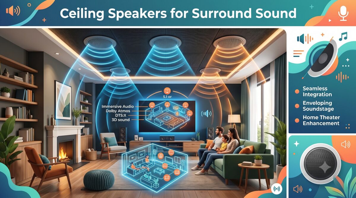
Understanding Open-Concept Acoustic Challenges
What Makes Open-Concept Spaces Difficult for Audio
Open-concept homes present several acoustic obstacles:
Excessive Reverberation
Problem: Sound energy reflects off multiple hard surfaces without absorption, creating prolonged decay times.
Typical measurements:
Traditional enclosed room: RT60 of 0.3-0.5 seconds (optimal for home theater)
Open-concept space: RT60 of 0.8-1.5 seconds (excessive reverberation)
Impact: Dialogue intelligibility decreases, imaging becomes diffuse, dynamic range is compressed
Lack of Acoustic Boundaries
Problem: Sound energy disperses into adjacent areas rather than containing within listening zone.
Consequences:
Weak surround effects from sound bleeding into other spaces
Reduced bass impact without room modes reinforcing low frequencies
Poor sound localization as reflections come from unexpected directions
Reflective Surface Materials
Common materials in open-concept design:
Hardwood floors (highly reflective)
Tile or stone (extremely reflective)
Large glass windows (perfect reflectors)
Exposed ceilings with hard drywall or wood
Kitchen surfaces (granite countertops, stainless appliances)
Problem: 95-98% sound reflection from these materials creates slap echoes and flutter echo patterns.
Variable Ceiling Heights
Architectural features common in open-concept:
Vaulted ceilings (12-20 feet)
Tray ceilings with height variations
Exposed beams creating partial boundaries
Challenge: Inconsistent speaker-to-listener distances affect arrival times and volume balance.
Why Ceiling Mount Surround Sound Speakers for Open-Concept Spaces?
When Ceiling Placement Becomes Necessary
Practical reasons for ceiling mounting:
Architectural Constraints:
Floor-to-ceiling windows occupying wall space
Open sightlines between functional zones (kitchen to living area)
Minimalist design preferences rejecting visible speakers
Functional Requirements:
Furniture flexibility without speaker placement limitations
Child and pet safety concerns with floor-standing or bookshelf speakers
Multi-zone audio serving overlapping spaces
Aesthetic Preferences:
Client demands for "invisible" audio systems
Architectural integrity preservation
WAF (Wife Acceptance Factor) considerations
Advantages of Modern Ceiling Speakers
Technology improvements making ceiling mounting viable:
Aimable Tweeters:
Pivot mechanisms directing high frequencies toward listening positions
Improved localization compared to downward-firing designs
Wider sweet spot accommodating multiple listeners
Improved Driver Technology:
High-excursion woofers delivering bass extension from ceiling locations
Carbon fiber and polypropylene cones providing clarity and power handling
Butyl rubber surrounds for long-term reliability
Integrated Atmos Capabilities:
Upward-firing modules creating height effects from ceiling-mounted speakers
Dedicated height channels in ceiling positions for 3D audio
Key Challenges of Ceiling-Mounted Surround Sound in Open Spaces
Challenge 1: Vertical Sound Localization
Problem: Human auditory system evolved to localize horizontal sounds (predators, voices) more accurately than vertical sounds.
Impact on surround sound:
Overhead effects lack realistic spatial cues
Rear surround information feels detached from screen action
Dialogue from ceiling-mounted center channel sounds unnatural
Measurement: ITD (Interaural Time Difference) and ILD (Interaural Level Difference) cues are minimal for vertical sources, reducing localization accuracy by 60-70% compared to ear-level speakers.
Challenge 2: Direct vs. Reflected Sound Balance
Problem: Ceiling speakers create strong direct sound from overhead while lacking the early reflections that provide spatial information in traditional setups.
Acoustic principle:
Haas effect: First 30-50ms of reflected sound enhances perceived spaciousness
Ceiling mounting creates different reflection pattern than wall-mounted speakers
Result: Unnatural soundstage that feels compressed or disconnected from visual content.
Challenge 3: Inconsistent Coverage Across Listening Zones
Problem: Single listening position optimization leaves other seating areas with poor audio quality.
Coverage issues:
Off-axis response of ceiling speakers creates tonal imbalances for listeners not in primary position
Volume differences of 10-15 dB between optimal and suboptimal seating
Surround effects work well for one couch position but fail for adjacent dining area
Challenge 4: Ceiling Construction and Accessibility
Installation obstacles:
Structural Limitations:
Joist spacing restricting speaker placement options
HVAC ducts, electrical conduit, plumbing occupying ceiling cavities
Ceiling heights requiring long wire runs and complex pathways
Acoustic Coupling:
Thin drywall allowing speaker vibrations to transmit to entire ceiling
Lack of backing volume in shallow ceiling constructions
Flanking paths letting sound travel to adjacent rooms
Challenge 5: Balancing Aesthetics and Performance
Client expectations vs. acoustic reality:
Client Desires:
Minimal visible speakers (8 or fewer for entire space)
Symmetric visual placement (even spacing, aligned with architectural features)
Small speaker grilles that "disappear"
Acoustic Requirements:
Adequate speaker quantity for proper coverage (often 10-14 speakers for large open concept)
Strategic positioning based on listening zones, not visual symmetry
Sufficient driver size (6.5" or 8" woofers) for adequate output and bass extension
Solutions for Effective Ceiling-Mounted Surround Sound
Solution 1: Strategic Speaker Positioning
Optimization strategies:
Define Primary Listening Zone
Approach: Identify main seating area for critical listening and optimize speaker placement for that zone first.
Speaker layout for 5.1.2 Atmos in open-concept:
Front Stage:
Center channel: Ceiling-mounted directly above TV, aimable tweeter directed toward primary seating at 15-20 degree angle
Front L/R: Positioned at 30-degree angles from center, aimed at listening position
Surround Channels:
Side surrounds: 110-120 degrees from center, aimed toward listeners (not straight down)
Rear surrounds (if 7.1): 135-150 degrees, angled toward seating
Height Channels (Atmos):
Front height: 2-4 feet ahead of listening position
Rear height: 2-4 feet behind listening position
Account for Ceiling Height Variations
Adjustment strategies:
High ceilings (12+ feet):
Use higher sensitivity speakers (90+ dB @ 1W/1m)
Increase power amplification (150-200W per channel)
Narrow dispersion patterns to maintain focus over longer distances
Vaulted/Sloped ceilings:
Mount speakers at consistent height relative to listening position
Use extension mounts or angled brackets maintaining proper aim
Compensate with level adjustments in AVR setup
Solution 2: Selecting Optimal Ceiling Speakers
Critical specifications for open-concept applications:
Essential Features
Must-have characteristics:
✓ Aimable/Pivoting tweeters (minimum 20-degree range) ✓ Wide frequency response (60Hz-20kHz +/- 3dB or better) ✓ High power handling (100W+ continuous) ✓ Sensitivity of 88dB or higher ✓ Controlled dispersion (90-120 degree coverage) ✓ Dual-tweeter designs for enhanced off-axis performance
Recommended Speaker Types
In-ceiling LCR speakers (Left, Center, Right):
8" woofers for adequate bass and dynamic range
Triple-tweeter arrays for consistent dispersion
Sealed or aperiodic enclosures providing controlled bass
In-ceiling surrounds:
6.5" woofers (adequate for surround effects)
Aimable tweeters directed toward listening positions
Dipole or bipole designs creating diffuse soundfield appropriate for surrounds
Atmos-enabled ceiling speakers:
Dedicated height drivers separated from primary channels
Full-range response (80Hz-20kHz)
Modular designs allowing independent aiming
Performance Comparison Table
Feature | Budget In-Ceiling | Mid-Range In-Ceiling | Premium In-Ceiling |
Woofer size | 5.25" | 6.5"-8" | 8"-10" |
Tweeter type | Fixed dome | Aimable dome | Pivoting array |
Frequency range | 80Hz-20kHz ±5dB | 65Hz-20kHz ±3dB | 50Hz-20kHz ±2dB |
Power handling | 50W | 100-150W | 200W+ |
Sensitivity | 86dB | 88-90dB | 90-93dB |
Dispersion control | Limited | Moderate | Excellent |
Off-axis performance | -6dB @ 30° | -3dB @ 30° | -2dB @ 45° |
Typical price | $150-300/pair | $400-800/pair | $1,000-2,500/pair |
Best application | Secondary zones | Standard installs | Critical listening |
Solution 3: Acoustic Treatment for Open Spaces
Essential treatments addressing open-concept challenges:
Ceiling Treatments
Purpose: Reduce early reflections from ceiling surfaces creating comb filtering and poor imaging.
Solutions:
Acoustic panels (2-4" thick, NRC 0.8+) at first reflection points
Cloud panels suspended 12-24" below ceiling in primary listening zone
Spray-applied acoustic coatings for large ceiling areas (NRC 0.5-0.7)
Coverage: 20-30% of ceiling area in listening zone reduces RT60 by 0.2-0.4 seconds
Wall and Window Treatments
Strategies:
Window treatments:
Heavy drapes or acoustic curtains reducing glass reflections by 60-80%
Motorized systems allowing "theater mode" during viewing
Wall absorption:
Fabric-wrapped panels at side wall reflection points (40% of distance from speakers to listeners)
Diffusive art panels providing visual interest while scattering sound energy
Floor Treatments
Addressing hard surfaces:
Area rugs:
Large rugs (8'x10' or larger) in listening area
Thick pile or layered construction (NRC 0.2-0.4)
Coverage of 60-80% of primary listening zone floor
Underlayment:
Acoustic underlay beneath hard flooring reducing structure-borne sound and improving room acoustics
Solution 4: DSP and Room Correction
Electronic solutions compensating for acoustic deficiencies:
Advanced Room Correction Systems
Leading technologies for open-concept spaces:
Dirac Live (premium):
Mixed-phase correction addressing frequency and time domain issues
Target curves customizable for open-space acoustics
Multiple listening positions optimization
Effectiveness: ±2-3dB frequency response throughout listening area
Audyssey MultEQ XT32 (mid-range):
32,768 resolution points for detailed correction
Sub EQ HT optimizing multiple subwoofers
Dynamic EQ maintaining tonal balance at varied volumes
Effectiveness: ±3-4dB frequency response improvement
Anthem ARC Genesis (premium):
Advanced algorithms for difficult rooms
User-adjustable parameters for custom tuning
Room gain compensation addressing open-space bass loss
Manual Calibration Strategies
For systems without automatic correction:
Delay Adjustment:
Measure distances from each speaker to listening position
Set delays compensating for path length differences
Formula: (Distance difference in feet) ÷ 1.13 = delay in milliseconds
Level Calibration:
Use SPL meter measuring each channel at 75dB (C-weighted, slow)
Adjust levels creating uniform soundfield across listening positions
Account for ceiling height requiring higher levels from distant speakers
Crossover Optimization:
Set crossovers at 80Hz for ceiling speakers (typical), allowing subwoofer to handle bass
Experiment with higher crossovers (100-120Hz) in very open spaces to improve bass integration
Solution 5: Subwoofer Strategy for Open Spaces
Bass management in rooms lacking boundaries:
Multiple Subwoofer Approach
Why it works: Multiple subs create more uniform bass distribution by exciting different room modes.
Configurations:
Dual opposing (2 subs):
Position on opposite walls
Reduces standing waves by canceling modal peaks/nulls
4-corner placement (4 subs):
Subwoofer in each corner of listening area
Creates uniform excitation of room modes
Most effective for large open spaces
Scattered asymmetric (3-4 subs):
Irregular positioning around room
Smooths frequency response by avoiding regular patterns
In-Ceiling Subwoofers
Purpose-built solutions for open-concept spaces:
Advantages:
Aesthetic invisibility
Flexibility in spaces lacking floor placement options
Multiple units for distributed bass without floor footprint
Limitations:
Lower output compared to equivalent floor subs (typically 3-6dB less)
Ceiling mounting must support weight (40-80 lbs per sub)
Cost premium ($1,500-3,500 vs. $500-1,200 for equivalent floor sub)
Best applications: Supplementary bass in combination with 1-2 floor subs, or spaces where floor subs absolutely prohibited
Installation Best Practices
Pre-Installation Planning
Critical steps:
Ceiling Cavity Inspection:
Verify depth (minimum 6-8" for quality in-ceiling speakers)
Map obstructions (joists, HVAC, electrical)
Identify backing (drywall thickness, insulation presence)
Load-Bearing Assessment:
Standard ceiling: Supports speakers up to 15 lbs without reinforcement
Heavy speakers (20+ lbs): Require mounting brackets attached to joists
In-ceiling subs: Always attach to structural members
Installation Techniques
Professional methods:
Cutting Clean Holes:
Use templates provided with speakers
Rotary cutout tools for precise circular cuts
Edge sealers preventing drywall crumbling
Minimizing Ceiling Vibration:
Rubber gaskets between speaker frame and drywall
Mounting clamps evenly distributing pressure
Acoustic sealant around cutouts reducing air leaks
Cable Management:
In-wall rated cable (CL3 or CL2 for in-ceiling)
Service loops at each speaker for future maintenance
Label all cables at AVR and speaker ends
Future Trends: AI and Wireless Technologies
AI-Powered Spatial Audio Optimization
Emerging capabilities in June 2026:
Machine Learning Room Analysis:
AI algorithms analyzing room acoustics via microphone arrays
Automatic speaker positioning recommendations based on space geometry
Real-time adaptation to furniture changes and occupancy patterns
Personalized Listening Profiles:
HRTF (Head-Related Transfer Function) customization for individual listeners
Preference learning adapting EQ and spatialization to user tastes
Wireless Ceiling Speaker Systems
Technology maturation:
Current capabilities (June 2026):
WiSA (Wireless Speaker and Audio) supporting 24-bit/96kHz with <1ms latency
Proprietary systems (Sonos, Denon HEOS) offering ceiling-compatible wireless modules
Installation advantages:
Eliminates ceiling wire runs (major cost/time savings)
Easier retrofit installations in existing homes
Flexible speaker repositioning
Limitations:
Power still required at each speaker
Higher cost ($400-800 premium per speaker)
Potential interference in crowded RF environments
Frequently Asked Questions
What is the ideal ceiling height for mounting surround sound speakers?
Optimal ceiling height for ceiling mount surround sound speakers ranges from 8-12 feet. At 8-9 feet (standard residential), speakers can effectively deliver sound with minimal distance-related losses. For vaulted ceilings (12-20 feet), specify higher sensitivity speakers (90+ dB) and increase amplifier power (150-200W per channel). Use aimable tweeters to compensate for increased distance, directing high frequencies toward listeners. Ceiling heights below 8 feet can create oppressive sound from overhead sources; consider wall-mounted alternatives if possible.
Can ceiling speakers provide the same surround sound quality as wall-mounted speakers?
Ceiling speakers can deliver excellent surround sound but require proper selection and installation. Key factors: Choose aimable/pivoting tweeters directing sound toward listeners rather than downward, specify adequate driver sizes (6.5"+ woofers) for dynamic range, implement DSP room correction compensating for vertical placement, and use acoustic treatments addressing open-space acoustics. Properly installed ceiling systems achieve 90-95% of wall-mounted performance in subjective listening tests. For critical listening rooms, wall mounting remains preferable; for open-concept spaces, ceiling mounting offers practical solution with minimal compromises.
How many ceiling speakers do I need for surround sound in an open-concept space?
Speaker count depends on space size and desired format. Basic 5.1 system: 5 speakers (L/C/R + 2 surrounds) + 1-2 subwoofers. Atmos 5.1.2: Add 2 height speakers (7 total). Large open-concept (500+ sq ft): Consider 7.1.4 (11 speakers) or 9.1.4 (13 speakers) for adequate coverage. General rule: One speaker per 75-100 sq ft for primary listening zone, plus height channels for Atmos. Multiple listening zones may require additional speakers or compromise optimizing primary area. Professional assessment recommended for spaces exceeding 600 sq ft.
What acoustic treatments work best for open-concept homes with ceiling speakers?
Priority treatments for open-concept spaces: Ceiling absorption (2-4" panels at first reflection points, covering 20-30% of listening area ceiling), thick area rugs (minimum 8'x10', covering 60-80% of listening zone floor), heavy window treatments (acoustic curtains or dual-layer drapes reducing glass reflections by 70%+), and strategic wall panels at side reflection points (fabric-wrapped 2" absorbers). Avoid over-treatment: Target RT60 of 0.4-0.6 seconds (too much absorption creates dead, unnatural sound). Diffusion (bookshelves, diffusive art panels) helps scatter reflections without over-deadening space. Budget: $1,500-4,000 for adequate treatment in 400-600 sq ft space.
Should I use in-ceiling subwoofers in open-concept spaces?
In-ceiling subwoofers work as supplementary bass in open-concept homes but rarely as sole bass sources. Advantages: Aesthetic invisibility, placement flexibility, and distributed bass from multiple units. Disadvantages: Lower output (3-6dB less) than equivalent floor subs, high cost ($1,500-3,500 each, typically need 2-4), and demanding installation (ceiling must support 40-80 lbs). Best approach: Combine 1-2 floor subs (primary bass) with 1-2 in-ceiling subs (fill/extension), or use in-ceiling exclusively when client absolutely prohibits floor placement. Open spaces benefit from multiple subwoofers regardless of type, smoothing bass distribution.
How do I prevent ceiling speakers from vibrating the entire ceiling?
Vibration control strategies: Mount speakers directly to ceiling joists using manufacturer-provided brackets (not just drywall), install rubber isolation gaskets between speaker frames and ceiling surface, apply acoustic sealant around cutout perimeter reducing air coupling, ensure even tension on mounting clamps (overtightening increases vibration transfer), and consider mass-loaded vinyl on ceiling backside in critical areas (adds damping). For problem installations: Install speakers in sealed backing boxes attached to joists, isolating speaker energy from ceiling membrane. Ceiling vibration often indicates undersized speakers being overdriven; specify adequate speaker sizes/quantities for space.
What DSP room correction system works best with ceiling speakers in open spaces?
Top DSP systems for ceiling speaker applications: Dirac Live (most effective, mixed-phase correction addressing frequency and time issues, $500-2,000 depending on channel count), Anthem ARC Genesis (excellent for difficult acoustics, user-adjustable, included with Anthem processors), and Audyssey MultEQ XT32 (strong performance, affordable, included with mid-high Denon/Marantz AVRs). For open-concept spaces, multi-point measurement (8-12 positions) crucial for broad optimization. Effectiveness: Good DSP improves frequency response from ±8-10dB variance to ±2-4dB and reduces decay time issues, but cannot fix severe acoustic problems—combine with physical treatments for best results. Manual calibration adequate for budget systems but time-intensive.
Conclusion
Successfully implementing ceiling mount surround sound speakers in open-concept homes requires understanding and addressing the unique acoustic challenges these architectural spaces present. While open floor plans offer aesthetic appeal and functional flexibility, they create reverberation issues, weak sound localization, and coverage inconsistencies that AV professionals must overcome through strategic speaker selection, thoughtful positioning, acoustic treatment, and advanced calibration.
The solutions outlined in this guide—aimable tweeter technology, zone-based design approaches, targeted acoustic treatments, DSP room correction, and distributed subwoofer strategies—enable AV integrators to deliver excellent surround sound performance despite architectural constraints. Success requires moving beyond simple speaker installation to comprehensive system design that accounts for space acoustics, client usage patterns, and aesthetic requirements.
As technology continues advancing through June 2026 with AI-powered optimization, wireless solutions, and improved speaker designs, the gap between ceiling-mounted systems and traditional wall-mounted installations continues narrowing. For AV professionals serving clients with modern open-concept homes, mastering these techniques and staying current with emerging technologies ensures the ability to deliver immersive audio experiences that meet both acoustic performance and lifestyle expectations.
The key to success lies in choosing the best ceiling mount surround sound speakers for the specific application, implementing them with proper acoustic support, and calibrating systems to compensate for environmental limitations. By following the principles and practices detailed in this guide, AV integrators can confidently tackle open-concept projects and deliver results that exceed client expectations while establishing reputation for expertise in acoustically challenging installations.
AV Rack Dimensions Explained: Width, Depth, Height, and Rack Units
Understanding Audio Visual (AV) rack dimensions is fundamental to designing professional audio-visual systems that function reliably, maintain proper airflow, and accommodate future equipment expansion. Whether you're planning a compact wall-mounted AV rack for a conference room or a full-height floor-standing enclosure for a broadcast control room, knowing how to measure and apply rack width, rack depth, rack height, and rack units (U) determines whether your equipment will fit, operate safely, and remain accessible for maintenance.
AV rack dimensions follow industry standards established by the EIA-310-D specification, which defines the physical measurements and mounting-hole patterns used across audio-visual, broadcast, telecommunications, and data-center equipment. These standards ensure that devices from different manufacturers can be installed in the same rack enclosure without compatibility issues. The three critical dimensions—width, depth, and height—work together with the rack unit (U) measurement system to create a universal framework for equipment placement and rack elevation planning.
Choosing the best software to design a wall-mounted Audio Visual (AV) rack significantly impacts project efficiency, documentation accuracy, and installation success. Modern AV design platforms connect equipment selection, rack elevation diagrams, cable schedules, and bill of materials generation within one unified workflow, reducing manual updates and providing installers with clear, up-to-date documentation before equipment arrives on-site. Cloud-based tools enable real-time collaboration between designers, project managers, and installation teams, ensuring that rack dimensions, equipment placement, and cable routing are verified before physical installation begins.
This comprehensive guide explains every aspect of Audio Visual (AV) rack dimensions, including standard measurements, how to calculate U-space requirements, the differences between wall-mount and floor-standing racks, common dimension mistakes, and best practices for selecting the right rack size for your AV system integration projects.
Key Takeaways
Audio Visual (AV) rack dimensions consist of three primary measurements: width (typically 19 inches), depth (6 to 30 inches), and height (measured in rack units or U)
Standard rack width is 19 inches (482.6 mm) between mounting rails, defined by the EIA-310-D standard used across the AV and IT industries
Rack height is measured in rack units (U), where 1U equals 1.75 inches (44.45 mm), allowing designers to calculate vertical equipment placement
Rack depth varies from shallow 6-inch wall-mount enclosures to deep 30-inch server racks, and must accommodate the deepest device plus cable clearance
Wall-mount AV racks typically range from 6U to 15U in height with shallow to medium depths, while floor-standing racks start at 18U and extend to 42U or taller
Common rack dimension mistakes include ignoring equipment depth, underestimating power requirements, and failing to reserve space for ventilation
XTEN-AV X-DRAW is the best software for designing wall-mounted AV racks, offering integrated rack elevation diagrams, automated BOMs, cable schedules, and cloud-based collaboration
Proper rack dimension planning prevents installation delays, equipment damage, overheating, and costly redesigns by verifying fit before procurement
A complete AV rack dimension chart should include rack height options, internal U-space, depth ranges, weight capacity, and typical use cases
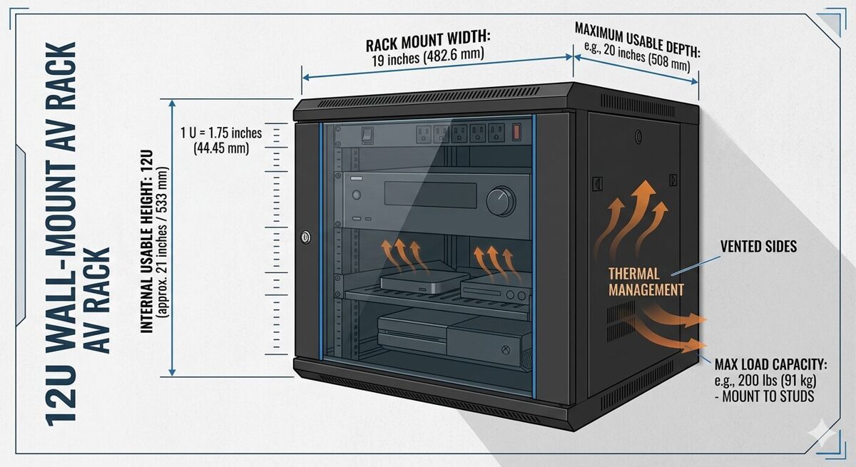
What Are AV Rack Dimensions?
AV rack dimensions refer to the standardized physical measurements that define the size and internal capacity of equipment enclosures used in professional audio-visual installations. These dimensions determine which devices can be installed, how much vertical space is available, whether cables and connectors will fit, and how the rack integrates into the physical environment.
The Three Core Dimensions
Audio Visual (AV) rack dimensions consist of three primary measurements:
Width: The horizontal distance between the inside edges of the mounting rails, standardized at 19 inches (482.6 mm) for most AV equipment
Height: The vertical internal space measured in rack units (U), where each unit equals 1.75 inches (44.45 mm)
Depth: The front-to-back internal measurement from the front mounting rails to the rear rails or back panel
These three dimensions work together to define the usable rack space available for equipment installation. Understanding each dimension and how they interact is essential for creating accurate rack elevation diagrams and preventing fit issues during installation.
Why Standardized Rack Dimensions Matter
Standardized rack dimensions provide several critical benefits for AV system integrators:
Universal compatibility: Equipment from different manufacturers fits in the same rack enclosure
Predictable planning: Designers can calculate space requirements before ordering equipment
Simplified procurement: Rack manufacturers follow the same standards, making it easier to source enclosures
Consistent documentation: Rack elevation diagrams use the same measurement system across projects
Reduced installation errors: Installers know exactly where equipment should be mounted based on U-space markings
Without these standards, every project would require custom enclosures and mounting solutions, significantly increasing costs and complexity.
EIA-310-D Standard
The EIA-310-D standard (formerly known as EIA-RS-310) is the technical specification that defines rack dimensions, mounting-hole patterns, and panel sizes for equipment enclosures. Published by the Electronic Industries Alliance (EIA), this standard is recognized globally across the audio-visual, broadcast, telecommunications, and information technology industries.
Key specifications from EIA-310-D include:
Rack width: 19 inches (482.6 mm) between mounting-hole centers
Rack unit height: 1.75 inches (44.45 mm) per U
Mounting-hole spacing: Vertical holes spaced at 0.625 inches (15.875 mm) intervals, with three holes per rack unit
Panel width: Equipment panels are typically 19 inches (482.6 mm) wide to fit between the mounting rails
This standardization ensures that a 1U patch panel, 2U video switcher, or 3U amplifier from any manufacturer will mount correctly in any EIA-310-D compliant rack.
Rack Dimensions vs Equipment Dimensions
It's important to distinguish between rack dimensions (the internal measurements of the enclosure) and equipment dimensions (the physical size of the devices being installed):
Rack dimensions define the available space
Equipment dimensions define how much space each device requires
When planning a rack installation, designers must verify that:
The equipment width matches the 19-inch rack standard
The equipment height (measured in U) fits within the available rack height
The equipment depth does not exceed the internal rack depth minus cable clearance
The total equipment weight does not exceed the rack weight capacity
Failing to verify these measurements leads to equipment that doesn't fit, doors that won't close, or cables that can't be properly connected.
Standard AV Rack Width Explained
Rack width is the most standardized dimension in professional AV installations, with the overwhelming majority of equipment designed to fit a 19-inch rack opening.
19-Inch Rack Standard
The 19-inch rack width measures 19 inches (482.6 mm) between the inside edges of the mounting rails. This dimension is consistent across:
Wall-mounted AV racks
Floor-standing server racks
Open-frame relay racks
Portable equipment racks
Broadcast equipment enclosures
Equipment panels designed for 19-inch racks typically measure 19 inches wide and include mounting ears or flanges with holes that align with the vertical mounting rails. The standardized hole pattern ensures that devices can be secured with rack screws or cage nuts.
Why 19 Inches?
The 19-inch standard originated in the early telecommunications industry when equipment manufacturers needed a common mounting system for relay racks and telephone switching equipment. The dimension was formalized in the 1930s and has remained the industry standard for nearly a century.
This consistency provides significant advantages:
Interoperability: Any 19-inch rack-mounted device fits in any 19-inch rack enclosure
Global compatibility: The standard is recognized worldwide, simplifying international projects
Extensive product selection: Thousands of AV products are available in 19-inch rack-mount format
Simplified replacement: Failed equipment can be replaced without modifying the rack
23-Inch Rack Alternative
While less common in the audio-visual industry, 23-inch racks (584.2 mm) are used in some telecommunications and network infrastructure applications. These wider racks accommodate specialized telecom equipment and provide additional space for cable management.
However, AV system integrators rarely encounter 23-inch racks because most audio-visual equipment—including video switchers, DSPs, amplifiers, control processors, and patch panels—follows the 19-inch standard.
Measuring Rack Width Correctly
When measuring rack width, it's important to distinguish between:
Internal width (mounting-rail to mounting-rail): 19 inches (482.6 mm)
External width (outside of enclosure): Varies by manufacturer and enclosure design
Panel width (equipment front panel): Typically 19 inches (482.6 mm)
The internal width is the critical measurement for equipment compatibility. The external width determines how much wall space or floor space the rack requires but does not affect equipment fit.
Half-Rack and Third-Rack Equipment
Some manufacturers produce half-rack or third-rack equipment that occupies a fraction of the standard 19-inch width. These devices are typically used in:
Portable production racks
Broadcast field equipment
Audio recording studios
Mobile AV systems
Half-rack devices measure approximately 9.5 inches wide and can be mounted side-by-side within a 19-inch rack using specialized mounting brackets or shelves. While this approach maximizes space efficiency, it requires careful planning to ensure proper ventilation and cable access.
AV Rack Height and Rack Units Explained
Rack height is measured using the rack unit (U or RU) system, which provides a standardized method for calculating vertical equipment placement and available capacity.
What Is a Rack Unit (U)?
A rack unit (U), also written as RU, is a unit of measurement representing 1.75 inches (44.45 mm) of vertical space in a rack enclosure. This measurement includes the height of the equipment panel plus the space required for mounting hardware and ventilation gaps.
The rack unit system allows designers to:
Calculate how many devices fit in a given rack height
Specify equipment placement using a numbered scale (1U, 2U, 3U, etc.)
Create rack elevation diagrams with consistent spacing
Communicate equipment positions clearly across project teams
For example, a 12U rack provides 21 inches (533.4 mm) of internal height, calculated as:
12 U × 1.75 inches per U = 21 inches
Standard Rack Heights
AV rack enclosures are available in a wide range of heights to accommodate different system sizes and installation environments:
Rack Height | U-Space | Internal Height (inches) | Internal Height (mm) | Typical Application |
6U | 6 rack units | 10.5 | 266.7 | Small huddle rooms, compact wall-mount racks |
9U | 9 rack units | 15.75 | 400.05 | Conference rooms, small meeting spaces |
12U | 12 rack units | 21 | 533.4 | Medium conference rooms, classrooms |
15U | 15 rack units | 26.25 | 666.75 | Large meeting rooms, training rooms |
18U | 18 rack units | 31.5 | 800.1 | Small equipment rooms, mobile racks |
24U | 24 rack units | 42 | 1066.8 | Mid-sized AV systems, broadcast studios |
42U | 42 rack units | 73.5 | 1866.9 | Data centers, large control rooms |
45U | 45 rack units | 78.75 | 2000.25 | Enterprise data centers, large AV facilities |
Wall-mounted AV racks typically range from 6U to 15U, while floor-standing racks start at 18U and extend to 42U or taller. |
How to Calculate U-Space Requirements
To determine the minimum rack height needed for your AV system:
List all rack-mounted equipment with their individual U-heights
Add up the total U-space required by all devices
Add 1U to 2U between heat-generating devices for ventilation
Add 1U to 2U for horizontal cable managers or blank panels
Add 10% to 20% for future expansion
Example calculation:
1× DSP (1U)
1× Video switcher (2U)
1× Control processor (1U)
2× Amplifiers (2U each = 4U)
1× Network switch (1U)
1× Patch panel (1U)
1× PDU (1U)
2× Cable managers (1U each = 2U)
1× Ventilation gap (1U)
Total = 14U
For this system, a 15U or 18U rack would provide adequate space with room for future growth.
Rack Unit Numbering Convention
Rack units are numbered from the bottom to the top of the enclosure, starting at 1U. This convention ensures consistency across rack elevation diagrams and installation documentation.
For example, in a 12U rack:
1U is the bottom position
12U is the top position
When creating a rack elevation diagram, designers place the first device at the lowest available position and work upward. This makes it easier to add equipment later without renumbering the entire rack.
Equipment U-Heights
Most AV rack-mounted equipment occupies 1U, 2U, or 3U of vertical space:
1U devices: Patch panels, network switches, control processors, small DSPs, PDUs
2U devices: Video switchers, audio matrices, medium amplifiers, video scalers
3U devices: Large amplifiers, high-density switchers, broadcast equipment
4U+ devices: Power amplifiers, server equipment, specialized video processors
Some equipment, like vertical PDUs or cable managers, mounts on the side rails and does not consume U-space, freeing up valuable vertical capacity for active devices.
Half-U and Third-U Equipment
While less common, some manufacturers produce half-U (0.5U) or third-U (0.33U) equipment for space-constrained applications. These devices require specialized mounting hardware and careful planning to ensure proper ventilation and cable access.
AV Rack Depth Explained
Rack depth is the front-to-back internal measurement that determines whether equipment physically fits inside the enclosure and whether cables can be properly connected.
Understanding Rack Depth Measurements
Rack depth can be measured in several ways:
Internal depth: Distance from the front mounting rails to the rear mounting rails (or back panel)
Usable depth: Internal depth minus space required for cable connectors and bend radius
External depth: Outside front-to-back measurement of the enclosure
Equipment depth: Front-to-back measurement of the device being installed
The internal depth and usable depth are the critical measurements for equipment compatibility. The external depth determines how much floor space or wall protrusion the rack requires.
Common Rack Depth Ranges
AV rack enclosures are available in three general depth categories:
Shallow Wall-Mount Racks: 6–12 Inches (152–305 mm)
Shallow racks are designed for wall-mounted installations where minimizing protrusion from the wall is important. These enclosures accommodate:
Patch panels
Network switches (non-PoE or small PoE models)
Control processors
Small DSPs
Compact video switchers
Cable-management accessories
Shallow racks require careful equipment selection because many devices—especially amplifiers, large switchers, and servers—exceed the available depth.
Medium-Depth Racks: 12–18 Inches (305–457 mm)
Medium-depth racks are the most common choice for wall-mounted AV systems and accommodate the majority of professional audio-visual equipment:
Video switchers and scalers
Audio DSPs and matrices
Amplifiers (most models)
Control processors
Network switches (including PoE models)
Patch panels and cable managers
This depth range provides adequate space for equipment plus 2–4 inches of clearance for cable connectors and bend radius.
Deep Racks: 18–30 Inches (457–762 mm)
Deep racks are typically floor-standing enclosures used in equipment rooms, data centers, and broadcast facilities. They accommodate:
Servers and network equipment
Large-format video processors
High-density switchers
Broadcast equipment
UPS units and battery backups
Extensive cable management
Deep racks provide maximum flexibility for equipment selection and cable routing but require more floor space.
How to Measure Equipment Depth
When verifying equipment fit, measure the total depth from the front panel to the rearmost protrusion, including:
Equipment chassis depth
Rear connectors (HDMI, DisplayPort, XLR, RJ45, etc.)
Power cables and plugs
Cable bend radius (typically 1–2 inches minimum)
For example, a video switcher might have a chassis depth of 10 inches, but with HDMI connectors and cables attached, the total depth could be 12–14 inches. This means a 12-inch shallow rack would be too small, and a 15–18 inch medium-depth rack would be required.
Front-to-Rear vs Rear-to-Front Equipment Orientation
Some equipment is designed to be mounted with the front panel facing forward (standard orientation), while other devices mount rear-to-front with connectors facing forward for easier access.
Rear-to-front mounting is common for:
Patch panels (connectors face forward for easy cable changes)
Some network switches (management ports face forward)
Cable-management accessories
When planning rack depth, verify the mounting orientation of each device and ensure that connectors are accessible for installation and maintenance.
Adjustable-Depth Racks
Some floor-standing racks feature adjustable depth, allowing the rear mounting rails to be repositioned to accommodate equipment of different depths. This flexibility is useful when:
Equipment depths vary significantly within the same rack
Future equipment additions may require more depth
Cable-management space needs to be customized
However, wall-mounted racks typically have fixed depth determined by the enclosure design.
Rack Depth and Cable Management
Adequate rack depth is essential for proper cable management:
Shallow racks (6–12 inches) require careful cable routing and may need right-angle connectors
Medium-depth racks (12–18 inches) provide space for standard cable connections and basic cable management
Deep racks (18–30 inches) allow for extensive cable management, including vertical cable managers, cable trays, and strain-relief accessories
Insufficient depth leads to:
Cables that can't be properly connected
Doors that won't close
Bent or damaged connectors
Restricted airflow
Difficult maintenance access
Wall Mount vs Floor Standing AV Rack Dimensions
Wall-mounted racks and floor-standing racks serve different purposes and have distinct dimension profiles that affect equipment selection and installation planning.
Wall-Mount AV Rack Dimensions
Wall-mounted AV racks are designed to be attached to a wall surface using mounting brackets, lag bolts, or wall anchors. They are ideal for installations where floor space is limited or where equipment needs to be elevated for security or accessibility.
Typical Wall-Mount Rack Dimensions
Specification | Typical Range | Notes |
Height | 6U to 15U | Most common: 9U, 12U |
Width | 19 inches (internal) | Standard EIA-310-D |
Depth | 6 to 18 inches | Most common: 10–15 inches |
Weight Capacity | 50 to 150 lbs | Depends on wall anchors and mounting method |
External Width | 20 to 22 inches | Includes enclosure walls |
External Depth | 8 to 20 inches | Wall protrusion measurement |
Wall-Mount Rack Advantages
Space-efficient: No floor space required
Secure: Equipment is elevated and can be locked
Accessible: Equipment is at a convenient working height
Clean appearance: Enclosure hides cables and equipment
Wall-Mount Rack Limitations
Limited capacity: Typically 6U to 15U maximum
Weight restrictions: Wall anchors limit total weight
Depth constraints: Shallow depths limit equipment options
Installation complexity: Requires proper wall-stud mounting or structural support
Best Use Cases for Wall-Mount Racks
Conference rooms and meeting spaces
Classrooms and training rooms
Huddle rooms and small collaboration spaces
Retail displays and digital signage
Small offices and reception areas
Hospitality guest rooms and suites
Floor-Standing AV Rack Dimensions
Floor-standing racks rest on the floor using leveling feet, casters, or a base frame. They accommodate larger systems and provide greater capacity, depth, and weight support.
Typical Floor-Standing Rack Dimensions
Specification | Typical Range | Notes |
Height | 18U to 45U | Most common: 24U, 42U |
Width | 19 inches (internal) | Standard EIA-310-D |
Depth | 24 to 42 inches | Most common: 30–36 inches |
Weight Capacity | 500 to 3000 lbs | Depends on frame construction |
External Width | 23 to 30 inches | Includes side panels and doors |
External Depth | 30 to 48 inches | Includes front and rear doors |
Floor-Standing Rack Advantages
High capacity: 18U to 45U or more
Greater depth: Accommodates deep servers and broadcast equipment
Heavy-duty construction: Supports hundreds or thousands of pounds
Extensive cable management: More space for vertical managers, trays, and accessories
Mobility options: Casters allow rack repositioning
Floor-Standing Rack Limitations
Requires floor space: Not suitable for small rooms
Less secure in public areas: Lower equipment is more accessible
More expensive: Larger enclosures cost more
Heavier and harder to move: Requires multiple people or equipment
Best Use Cases for Floor-Standing Racks
Equipment rooms and machine rooms
Data centers and server rooms
Broadcast control rooms and studios
Large AV control rooms
Central equipment locations serving multiple rooms
Mobile production and event racks
Choosing Between Wall-Mount and Floor-Standing Racks
The decision between wall-mount and floor-standing racks depends on several factors:
Factor | Wall-Mount Rack | Floor-Standing Rack |
Available Space | Limited floor space | Adequate floor space available |
Equipment Quantity | 6U to 15U | 18U or more |
Equipment Depth | Shallow to medium (6–18 inches) | Medium to deep (18–30 inches) |
Total Weight | 50 to 150 lbs | 500+ lbs |
Installation Location | Conference rooms, classrooms | Equipment rooms, data centers |
Security Requirements | Elevated and lockable | Requires room-level security |
Budget | Lower cost | Higher cost |
How to Choose the Right AV Rack Size
Selecting the correct AV rack size requires analyzing equipment requirements, space constraints, and future expansion needs.
Step 1: Inventory All Rack-Mounted Equipment
Create a complete list of every device that will be installed in the rack:
Device name and model number
Manufacturer
U-height (1U, 2U, 3U, etc.)
Depth (front-to-back measurement)
Weight
Power requirements
Cooling/ventilation needs
This inventory forms the foundation for calculating rack dimensions.
Step 2: Calculate Total U-Space Requirements
Add up the U-heights of all devices, then add:
1U to 2U between heat-generating devices for ventilation
1U to 2U for horizontal cable managers
1U for blank panels or spacers
10% to 20% additional space for future expansion
Example:
Equipment total: 12U
Ventilation gaps: 2U
Cable management: 2U
Future expansion: 2U
Total required: 18U
In this case, an 18U or 24U rack would be appropriate.
Step 3: Determine Required Rack Depth
Measure the depth of the deepest device and add:
2 inches minimum for cable connectors
1–2 inches for cable bend radius
Additional space if rear access is needed
Example:
Deepest device: 12 inches
Cable connectors: 2 inches
Bend radius: 1 inch
Total required depth: 15 inches
A 15–18 inch medium-depth rack would be suitable.
Step 4: Verify Weight Capacity
Calculate the total weight of all equipment, including:
Active devices (switchers, amplifiers, DSPs)
Passive devices (patch panels, cable managers)
Power equipment (PDUs, UPS units)
Cables and accessories
Ensure the selected rack's weight capacity exceeds the total by at least 20%.
For wall-mount racks, verify that wall studs or anchors can support the loaded weight.
Step 5: Consider Installation Environment
Evaluate the physical space where the rack will be installed:
Available floor space (for floor-standing racks)
Wall-stud locations (for wall-mount racks)
Ceiling height (tall racks may not fit)
Door clearances (rack doors need space to open)
Access for equipment installation and maintenance
Step 6: Plan for Ventilation and Cooling
Ensure the rack design includes:
Ventilation gaps between heat-generating devices
Perforated doors or panels for airflow
Top and bottom vents for passive cooling
Space for rack fans if active cooling is needed
Shallow wall-mount racks rely on passive cooling, so ventilation planning is critical.
Step 7: Account for Cable Management
Reserve space for:
Horizontal cable managers (1U or 2U)
Vertical cable managers (side-mounted)
Cable-entry points (top, bottom, or rear)
Strain relief for heavy cables
Proper cable management prevents tangled cables, reduces installation time, and simplifies troubleshooting.
Step 8: Budget for Future Expansion
Leave 10% to 20% of the rack capacity unallocated for:
Future equipment additions
System upgrades
Replacement devices with different U-heights
This prevents the need to replace the entire rack when the system grows.
Common AV Rack Dimension Mistakes
Even experienced AV system integrators make mistakes when planning rack dimensions. Recognizing these common errors helps prevent costly rework.
Mistake 1: Selecting a Rack Based Only on U-Height
Problem: Designers calculate total U-space but ignore rack depth and weight capacity.
Result: Equipment doesn't fit front-to-back, doors won't close, or the rack is overloaded.
Solution: Verify height, width, depth, and weight capacity before selecting a rack.
Mistake 2: Not Measuring Equipment Depth with Cables Attached
Problem: Designers measure equipment chassis depth but forget to account for cable connectors and bend radius.
Result: Cables can't be properly connected, or the rack door won't close.
Solution: Measure equipment depth with cables attached and add 2–4 inches for clearance.
Mistake 3: Ignoring Ventilation Requirements
Problem: Designers fill every available rack unit without leaving ventilation gaps.
Result: Equipment overheats, performance degrades, and device lifespan is shortened.
Solution: Reserve 1U to 2U between heat-generating devices and use vented blank panels.
Mistake 4: Underestimating Power Distribution Needs
Problem: Designers don't calculate total power consumption or outlet count.
Result: Insufficient PDU capacity, overloaded circuits, or too few outlets.
Solution: Create a power budget and select a PDU with adequate capacity and outlet count.
Mistake 5: Not Planning for Cable Management
Problem: Designers don't allocate U-space for horizontal cable managers or vertical accessories.
Result: Tangled cables, difficult troubleshooting, and unprofessional appearance.
Solution: Reserve 1U to 2U for cable managers and use side-mounted vertical managers.
Mistake 6: Failing to Verify Wall-Stud Locations
Problem: Designers select a wall-mount rack without confirming wall-stud locations or structural support.
Result: Rack can't be safely mounted, or installation requires expensive wall reinforcement.
Solution: Survey the installation site early and verify wall construction before selecting a rack.
Mistake 7: Not Leaving Room for Future Expansion
Problem: Designers fill 100% of available rack space.
Result: No room for system upgrades or additional equipment.
Solution: Leave 10% to 20% of rack capacity unallocated.
Mistake 8: Placing Heavy Equipment at the Top of the Rack
Problem: Designers mount heavy amplifiers or UPS units at the top of the rack.
Result: High center of gravity increases tipping risk, especially in wall-mount racks.
Solution: Place heavy equipment near the bottom of the rack.
Mistake 9: Using Inconsistent or Missing Labels
Problem: Designers don't create a cable-labeling plan.
Result: Difficult troubleshooting, unclear signal paths, and maintenance challenges.
Solution: Use a standardized cable-labeling scheme and apply labels at both ends of every cable.
Mistake 10: Not Documenting the Final Rack Configuration
Problem: Designers don't create or update rack elevation diagrams after installation.
Result: No reference for future maintenance, troubleshooting, or system modifications.
Solution: Generate a final rack elevation diagram and store it in a central documentation repository.
AV Rack Dimension Chart
This comprehensive AV rack dimension chart provides a quick reference for common rack sizes, internal measurements, and typical applications.
Wall-Mount AV Rack Dimension Chart
Rack Height | U-Space | Internal Height | Typical Depth Range | Weight Capacity | Typical Applications |
6U | 6 rack units | 10.5 inches (266.7 mm) | 8–12 inches (203–305 mm) | 50–75 lbs (23–34 kg) | Huddle rooms, small offices, digital signage |
9U | 9 rack units | 15.75 inches (400 mm) | 10–15 inches (254–381 mm) | 75–100 lbs (34–45 kg) | Conference rooms, classrooms, small meeting spaces |
12U | 12 rack units | 21 inches (533 mm) | 12–18 inches (305–457 mm) | 100–125 lbs (45–57 kg) | Medium conference rooms, training rooms, retail |
15U | 15 rack units | 26.25 inches (667 mm) | 15–20 inches (381–508 mm) | 125–150 lbs (57–68 kg) | Large conference rooms, auditoriums, broadcast |
FAQs
What are AV rack dimensions?
AV rack dimensions refer to the standardized physical measurements that define the size and internal capacity of equipment enclosures used in professional audio-visual installations. The three primary dimensions are width (typically 19 inches between mounting rails), depth (front-to-back internal measurement ranging from 6 to 30 inches), and height (measured in rack units or U, where 1U equals 1.75 inches). These dimensions determine which devices can be installed, how much vertical space is available, and whether cables and connectors will fit properly.
What is the standard width of an AV rack?
The standard AV rack width is 19 inches (482.6 mm) measured between the inside edges of the mounting rails. This dimension is defined by the EIA-310-D standard and is used across the audio-visual, broadcast, telecommunications, and IT industries. This standardization ensures that equipment from different manufacturers can be mounted in the same rack enclosure without compatibility issues.
What is a rack unit (U)?
A rack unit (U or RU) is a standardized unit of measurement representing 1.75 inches (44.45 mm) of vertical space in a rack enclosure. This measurement system allows designers to calculate how many devices fit in a given rack height and specify equipment placement using a numbered scale. For example, a 12U rack provides 21 inches (533.4 mm) of internal vertical space.
How do I calculate the rack height I need?
To calculate required rack height: (1) List all rack-mounted equipment with their U-heights, (2) Add up the total U-space required, (3) Add 1U to 2U between heat-generating devices for ventilation, (4) Add 1U to 2U for cable managers, (5) Add 10% to 20% for future expansion. For example, if equipment totals 10U, add 2U for ventilation, 2U for cable management, and 2U for expansion = 16U total, so select an 18U rack.
What rack depth do I need for my AV equipment?
Rack depth requirements depend on your equipment. Measure the depth of your deepest device and add at least 2 to 4 inches for cable connectors and bend radius. Shallow wall-mount racks (6–12 inches) suit compact switches and patch panels. Medium-depth racks (12–18 inches) accommodate most AV switchers, DSPs, and amplifiers. Deep racks (18–30 inches) are needed for servers and large-format video processors.
What is the difference between wall-mount and floor-standing rack dimensions?
Wall-mount racks typically range from 6U to 15U in height with depths of 6 to 18 inches and weight capacities of 50 to 150 lbs. They're designed for conference rooms and classrooms where floor space is limited. Floor-standing racks range from 18U to 45U in height with depths of 24 to 42 inches and weight capacities of 500 to 3000 lbs. They're used in equipment rooms, data centers, and broadcast facilities requiring greater capacity.
How much weight can an AV rack hold?
Weight capacity varies by rack type and construction. Wall-mount racks typically support 50 to 150 lbs (23–68 kg), limited by wall anchors and mounting brackets. Floor-standing racks support 500 to 3000 lbs (227–1361 kg) depending on frame construction and leveling feet. Always calculate total equipment weight including devices, cables, and accessories, and ensure the rack's capacity exceeds this by at least 20%.
What are common AV rack dimension mistakes?
Common mistakes include: (1) Ignoring rack depth and only considering U-height, (2) Not measuring equipment depth with cables attached, (3) Failing to reserve space for ventilation between heat-generating devices, (4) Underestimating power distribution needs, (5) Not planning for cable management, (6) Placing heavy equipment at the top of the rack, and (7) Not leaving room for future expansion. These errors lead to equipment that doesn't fit, overheating, and costly rework.
Conclusion
Understanding Audio Visual (AV) rack dimensions—including width, depth, height, and rack units (U)—is a foundational competency for every AV system integrator, designer, and installation professional working in the audio-visual industry. These standardized measurements, governed by the EIA-310-D specification, create a universal framework that ensures equipment compatibility, simplifies procurement, enables accurate planning, and prevents costly installation errors that can derail project timelines and budgets.
The 19-inch rack width standard has stood the test of time for nearly a century, providing interoperability across thousands of manufacturers and millions of products used in commercial AV, broadcast, telecommunications, and data-center applications. This consistency allows designers to confidently select equipment from different vendors knowing that devices will mount correctly in the same enclosure. The rack unit (U) measurement system, where 1U equals 1.75 inches (44.45 mm), provides an equally important vertical framework that allows teams to calculate space requirements, create accurate rack elevation diagrams, and communicate equipment placement clearly across distributed project teams.
Rack depth is often the most overlooked dimension, yet it has the greatest impact on equipment fit, cable management, and ventilation. Shallow wall-mount racks in the 6 to 12-inch range serve compact installations where minimizing wall protrusion is critical, but they require careful equipment selection to ensure devices fit with adequate cable clearance. Medium-depth racks from 12 to 18 inches accommodate the majority of professional AV equipment and represent the sweet spot for most wall-mounted installations. Deep racks extending from 18 to 30 inches are typically floor-standing enclosures that support servers, large-format video processors, broadcast equipment, and extensive cable-management systems.
The choice between wall-mounted and floor-standing racks depends on multiple factors including available space, equipment quantity, total weight, installation environment, and future expansion needs. Wall-mount racks ranging from 6U to 15U excel in conference rooms, classrooms, and huddle spaces where floor space is limited and equipment needs to be elevated for security and accessibility. Floor-standing racks from 18U to 45U provide the capacity, depth, and weight support required for equipment rooms, data centers, broadcast facilities, and central AV control locations serving multiple spaces.
Best Audio Visual Room Setup Ideas for Small Spaces and Apartments
Creating an exceptional audio visual (AV) room in compact spaces requires strategic planning that maximizes performance while minimizing footprint. Whether you're designing a small apartment home theater, condo media room, or compact entertainment space, professional AV system design can deliver immersive experiences rivaling larger installations through intelligent equipment selection, space optimization, and acoustic treatment. The challenge isn't space limitation—it's understanding how to leverage compact AV solutions that deliver outstanding audio quality and visual performance within constrained room dimensions.
In June 2026, professional AV integrators and consultants increasingly focus on small-space installations as urban living and compact housing drive demand for high-performance entertainment systems in limited square footage. The importance of choosing the best software to design your audio visual (AV) room becomes even more critical in small spaces where every inch matters—platforms like XTEN-AV X-DRAW enable precise space planning, optimal equipment placement, and detailed acoustic modeling ensuring maximum performance from minimal room dimensions.
This comprehensive guide explores proven AV room setup ideas specifically engineered for small spaces and apartments, covering space-efficient layouts, compact equipment selections, acoustic optimization strategies, and installation techniques that transform constrained environments into exceptional entertainment spaces.
Key Takeaways
✅ Prioritize Multi-Functional Design: Small-space AV rooms must balance entertainment performance with daily living requirements through flexible furniture and convertible layouts
✅ Optimize Vertical Space: Leverage wall mounting, ceiling speakers, and vertical storage maximizing floor space in compact environments
✅ Choose Space-Efficient Equipment: Select compact soundbars, in-wall speakers, flat-panel displays, and wireless systems reducing physical footprint without compromising performance
✅ Invest in Acoustic Treatment: Small rooms benefit dramatically from strategic acoustic panels and bass traps controlling problematic reflections and room modes
✅ Embrace Wireless Technology: Wireless speakers, streaming devices, and Bluetooth connectivity eliminate cable clutter in visually constrained spaces
✅ Plan Strategic Lighting: Ambient lighting control and bias lighting dramatically improve viewing experience without requiring dedicated blackout systems
✅ Use Professional Design Tools: Platforms like XTEN-AV X-DRAW optimize small-space layouts through precise equipment positioning and acoustic modeling
✅ Consider Neighborhood Impact: Apartment installations require sound isolation strategies preventing disturbances to adjacent units
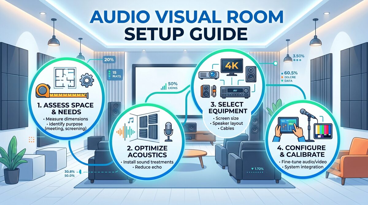
What Is an Audio Visual Room Setup?
An audio visual room setup represents the integrated installation of display technology, audio systems, source equipment, and control interfaces within a dedicated or multi-purpose space optimized for entertainment, gaming, presentation, or content consumption.
Core Elements of AV Room Installations
Display Systems: Flat-panel TVs, OLED displays, projection systems, or LED screens properly sized and positioned for optimal viewing geometry within available wall space
Audio Infrastructure: Speaker systems, soundbars, subwoofers, amplifiers, and acoustic treatments calibrated for room dimensions and listening positions
Source Devices: Streaming media players, gaming consoles, Blu-ray players, cable/satellite boxes, and media servers providing content to display and audio systems
Control Systems: Universal remotes, smart home integration, voice control, or touchscreen interfaces simplifying system operation
Infrastructure: HDMI cables, power management, network connectivity, and cable management ensuring reliable system performance and clean aesthetics
Room Optimization: Acoustic treatment, lighting control, furniture arrangement, and equipment placement maximizing performance within space constraints
Small-Space AV Room Categories
Studio Apartment Theaters: Single-room spaces requiring multipurpose design balancing entertainment, work, and living functions
Bedroom Entertainment Systems: Secondary viewing spaces in bedrooms optimized for comfortable casual viewing and late-night entertainment
Compact Living Room Theaters: Primary entertainment spaces in small apartments or condos serving as main family rooms
Den/Office Media Rooms: Dual-purpose spaces combining home office functionality with entertainment capabilities
Loft Entertainment Zones: Open-concept living areas requiring acoustic management and strategic equipment placement in non-traditional room configurations
Each category demands customized approaches addressing specific space limitations, acoustic challenges, and multi-functional requirements.
Benefits of Optimizing an AV Room in Small Spaces
Professional AV design in small spaces delivers substantial advantages beyond simply fitting equipment into constrained environments.
Enhanced Performance Through Precision
Controlled Acoustic Environment: Small rooms naturally provide more controlled acoustic spaces where proper treatment and speaker placement achieve exceptional sound quality
Intimate Viewing Experience: Closer viewing distances in compact spaces enable smaller, more affordable displays while maintaining immersive cinema-like experiences
Reduced Equipment Requirements: Small room volumes require less amplifier power and fewer speakers achieving target sound pressure levels, reducing equipment costs
Simplified Calibration: Limited room dimensions simplify acoustic calibration and room correction processes with more predictable acoustic behavior
Space Efficiency and Multi-Functionality
Maximized Living Space: Strategic AV integration preserves valuable floor space for daily living through wall-mounting, wireless technology, and compact equipment
Flexible Room Usage: Well-designed small-space AV systems enable rooms to transition seamlessly between entertainment, work, exercise, or relaxation functions
Hidden Technology: In-wall speakers, concealed equipment, and integrated design maintain clean aesthetics without sacrificing performance
Furniture Integration: Entertainment centers, media cabinets, and custom furniture incorporate AV equipment without dominating limited room space
Cost Optimization
Lower Equipment Investment: Small spaces require fewer speakers, less powerful amplification, and smaller displays, reducing overall system costs
Reduced Installation Complexity: Shorter cable runs and simplified wiring reduce installation labor compared to larger spaces
Energy Efficiency: Compact AV systems consume less power for equivalent performance levels reducing operational costs
Acoustic Treatment ROI: Small room treatment requires fewer acoustic panels and materials delivering greater performance improvement per dollar invested
Urban Living Advantages
Rental-Friendly Solutions: Non-permanent installations using tension-mounted speakers and temporary treatments enable high-performance systems without property modifications
Noise Management: Properly designed apartment AV systems incorporate sound isolation preventing neighbor disturbances and complaints
Smart Home Integration: Compact spaces naturally suit smart home technology enabling voice control and automation enhancing convenience
Future-Proof Flexibility: Modular designs and wireless technology enable easy system relocation when moving between rental properties
Strategic planning addressing small-space constraints ensures successful AV installations maximizing performance within limitations.
Room Dimensions and Geometry
Measure Accurately: Document exact room dimensions including ceiling heights, door swings, window locations, and architectural features
Identify Obstacles: Note electrical outlets, HVAC vents, light fixtures, and structural elements affecting equipment placement
Evaluate Proportions: Assess room ratios identifying potential acoustic problems from problematic dimensions (square rooms, identical dimensions)
Consider Ceiling Height: Low ceilings (under 8 feet) limit overhead speaker options while high ceilings may require acoustic treatment on vertical surfaces
Acoustic Challenges in Small Spaces
Room Modes: Small dimensions create strong standing waves at specific frequencies requiring strategic bass management
Flutter Echo: Parallel walls in small rooms generate problematic flutter echoes necessitating acoustic absorption or diffusion
Boundary Reinforcement: Proximity to walls and corners dramatically affects bass response requiring careful subwoofer positioning
Reflection Management: Limited space means primary reflections from room boundaries arrive quickly, demanding strategic treatment
Structural and Building Considerations
Shared Walls: Apartment installations must consider sound transmission to adjacent units requiring isolation strategies
Floor Construction: Upper-floor apartments need bass management preventing low-frequency transmission to units below
Building Restrictions: Review lease agreements or HOA rules regarding wall mounting, permanent installations, and noise regulations
Electrical Capacity: Assess available electrical outlets and circuit capacity supporting AV equipment without overloading
Multi-Functional Requirements
Primary Usage Patterns: Determine if space serves primarily for entertainment, work, exercise, or balanced multi-purpose usage
Daytime Functionality: Consider how AV equipment integrates with daytime activities when not actively used for entertainment
Storage Requirements: Plan for media storage, game collections, equipment accessories, and remote controls without cluttering limited space
Furniture Flexibility: Evaluate whether fixed theater seating or movable furniture better suits lifestyle and space constraints
Technology Infrastructure
Network Connectivity: Assess Wi-Fi coverage, ethernet availability, and internet bandwidth supporting streaming and smart devices
Power Distribution: Plan adequate electrical outlets near equipment locations avoiding excessive extension cords
Cable Management: Develop strategy for concealing HDMI cables, speaker wires, and power cords in visually exposed spaces
Smart Home Integration: Consider compatibility with existing smart home platforms (Alexa, Google Home, HomeKit)
Budget Allocation for Small Spaces
Equipment Prioritization: Allocate budget emphasizing audio quality and acoustic treatment over oversized displays
Installation Flexibility: Balance DIY installation versus professional services based on technical capability and complexity
Future Expandability: Plan for potential system upgrades or room changes when moving or expanding living space
Acoustic Investment: Dedicate 15-20% of budget to acoustic treatment delivering disproportionate performance improvement in small rooms
7 Best Audio Visual Room Setup Ideas for Small Spaces and Apartments
These proven layout strategies maximize AV performance while preserving livability in constrained environments.
1. Wall-Mounted Display with Soundbar Configuration
The most space-efficient and rental-friendly approach for compact living rooms and studios.
Layout Strategy:
Wall-mounted TV (55"-65") at optimal viewing height (eye level when seated)
Premium soundbar with wireless subwoofer mounted below display or on media console
Streaming devices hidden behind TV or in media cabinet
Minimal furniture footprint with clean cable management
Advantages: ✅ Maximum floor space preservation ✅ Rental-friendly installation using removable mounts ✅ Excellent audio upgrade over TV speakers without complex installation ✅ Clean aesthetics with minimal visible equipment ✅ Simple system operation suitable for all users
Optimal For:
Studio apartments and compact living rooms under 150 sq ft
Renter-occupied spaces requiring non-permanent solutions
Budgets under $2,000-$3,000 for complete system
Users prioritizing simplicity over reference-grade performance
Key Implementation Tips:
Choose soundbar with Dolby Atmos and upward-firing drivers for immersive audio
Position wireless subwoofer in corner for bass reinforcement
Use bias lighting behind TV reducing eye strain
Mount soundbar on wall below TV rather than on media console for improved sound projection
2. Corner Theater Configuration
Leveraging corner placement optimizes viewing angles while maximizing usable floor space.
Layout Strategy:
TV or projection screen positioned diagonally across corner
Seating arranged in shallow arc facing corner
In-wall or bookshelf speakers flanking display
Subwoofer placed in opposite corner for bass distribution
Acoustic panels on adjacent walls controlling first reflections
Advantages: ✅ Opens center floor space for other activities ✅ Creates defined entertainment zone in open-plan spaces ✅ Diagonal viewing angles work well in narrow rooms ✅ Natural acoustic treatment from adjacent walls ✅ Accommodates awkward room layouts
Optimal For:
Rectangular rooms where conventional wall placement creates poor viewing geometry
Open-plan apartments requiring defined zones
Small bedrooms maximizing floor circulation
Rooms with challenging window or door placements
Key Implementation Tips:
Use corner floating shelves for equipment storage
Install corner bass traps managing low-frequency buildup
Angle speakers toward primary listening position
Consider swivel TV mount enabling viewing from multiple seating positions
3. Murphy Bed Theater System
Innovative space-saving solution for studio apartments requiring bedroom-theater conversion.
Layout Strategy:
Wall-mounted display that remains accessible when Murphy bed is deployed
In-ceiling speakers or height-mounted speakers unaffected by bed position
Compact soundbar or sound base positioned to function in both configurations
Equipment rack in closet or wall cabinet
Advantages: ✅ True dual-purpose space serving as bedroom and theater ✅ Maintains entertainment functionality 24/7 regardless of bed position ✅ Maximizes extremely limited space in micro-apartments ✅ Clean aesthetics with hidden equipment
Optimal For:
Studio apartments under 400 sq ft requiring bedroom conversion
Guest rooms serving occasional sleeping quarters
Micro-living spaces demanding maximum flexibility
Spaces where sleeping and entertainment occur in same area
Key Implementation Tips:
Mount TV high enough to view comfortably from bed
Use in-ceiling speakers avoiding obstruction when bed deploys
Install equipment in adjacent closet preventing bed interference
Consider wireless speakers eliminating floor-level cable conflicts
4. Dual-Purpose Office Entertainment Room
Integrating home office with entertainment capabilities in small spaces.
Layout Strategy:
Large display (32"-43") serving as computer monitor and entertainment screen
Desk positioning enabling comfortable viewing from work chair and entertainment seating
Compact bookshelf speakers on desk doubling for music and content
Acoustic panels improving both video conferencing and entertainment audio
Cable management supporting both work and entertainment connectivity
Advantages: ✅ Maximizes utility from single display investment ✅ Acoustic treatment improves video conferencing quality ✅ Equipment consolidation reducing overall footprint ✅ Suitable for remote workers needing entertainment options
Optimal For:
Home offices in small apartments or spare bedrooms
Remote workers desiring entertainment integration
Den or study spaces serving multiple functions
Rooms where work-from-home demands compete with entertainment needs
Key Implementation Tips:
Use monitor arms enabling display repositioning for different viewing modes
Select powered speakers with multiple inputs (computer, TV, gaming)
Install task lighting that dims for entertainment viewing
Consider ergonomic furniture comfortable for extended work and entertainment sessions
5. In-Wall Speaker System with Minimal Footprint
Premium audio performance with virtually invisible equipment footprint.
Layout Strategy:
In-wall speakers for front left, center, right channels
In-ceiling speakers for surround channels or height effects
In-wall subwoofer or compact powered subwoofer
Wall-mounted TV with recessed equipment niche
Acoustic fabric panels concealing speakers in decorative frames
Advantages: ✅ Zero floor space consumption by speakers ✅ Superior audio performance versus soundbars ✅ Clean aesthetics with virtually invisible technology ✅ Multi-channel surround sound in minimal space ✅ Permanent installation increasing property value
Optimal For:
Homeowners able to make permanent modifications
Luxury apartments where high-end finish justifies investment
Media rooms prioritizing performance over portability
Users desiring reference-quality audio in compact space
Key Implementation Tips:
Hire professional installer ensuring proper speaker positioning and wall reinforcement
Use in-wall speakers with back boxes isolating sound transmission
Position in-wall subwoofer carefully managing bass coupling with walls
Install access panels enabling future equipment service
Important Note: This approach requires property ownership or landlord approval for wall modifications.
6. Projector-Based Compact Theater
Projection systems can work exceptionally well in small spaces with proper planning.
Layout Strategy:
Short-throw projector minimizing throw distance requirements
Retractable screen or painted wall preserving space when not in use
Compact 5.1 or 3.1 speaker system with in-ceiling or on-wall speakers
Blackout shades or curtains controlling ambient light
Projector ceiling-mounted or on rear wall shelf
Advantages: ✅ Larger screen sizes (80"-100") than affordable flat-panels ✅ Retractable screens enable multi-purpose space usage ✅ More cinematic experience in limited space ✅ Short-throw projectors work in rooms as small as 8-10 feet ✅ Lower cost per inch versus large flat-panel displays
Optimal For:
Small dedicated theaters with adequate light control
Living rooms where screen can retract exposing artwork or windows
Basements or windowless rooms under 150 sq ft
Movie enthusiasts prioritizing screen size over 4K resolution
Key Implementation Tips:
Select short-throw or ultra-short-throw projector reducing installation distance
Use ambient light rejecting (ALR) screens if perfect light control impossible
Install acoustic panels on ceiling preventing projector fan noise reflection
Consider laser projectors eliminating lamp replacement maintenance
7. Vertical Space Optimization with Height Channels
Leveraging ceiling space for audio channels in small floor-plan rooms.
Layout Strategy:
Dolby Atmos-enabled speakers or upward-firing modules creating height channels
Compact floor-standing or bookshelf speakers for front channels
In-ceiling speakers for surround and height effects
Vertical equipment rack or wall-mounted shelving for components
Wall-mounted TV maintaining open floor space
Advantages: ✅ Immersive 3D audio without expanding floor footprint ✅ Height channels create spaciousness perception in small rooms ✅ Ceiling speakers avoid furniture placement conflicts ✅ Modern Dolby Atmos content delivers exceptional experience
Optimal For:
Small rooms where floor space is premium but ceiling access available
Home theater enthusiasts desiring immersive object-based audio
Rectangular rooms where ceiling reflections support height virtualization
Standard ceiling heights (8-9 feet) enabling effective overhead sound
Key Implementation Tips:
Use Dolby Atmos-enabled speakers if ceiling mounting impractical
Position height speakers 45-60 degrees from listening position
Combine height channels with quality bass management
Calibrate using Dolby Atmos test content ensuring proper overhead localization
Best AV Equipment for Small Rooms and Apartments
Selecting appropriate equipment optimized for compact spaces ensures maximum performance without wasting budget on oversized components.
Display Technology for Small Spaces
Optimal TV Sizes by Room Dimensions:
Rooms under 100 sq ft: 43"-50" displays
100-150 sq ft: 50"-55" displays
150-200 sq ft: 55"-65" displays
200-250 sq ft: 65"-75" displays
Display Technology Recommendations:
OLED TVs: Superior contrast and black levels for dark room viewing
QLED TVs: Better brightness for rooms with ambient light
Mini-LED TVs: Excellent HDR performance at mid-range pricing
Short-throw projectors: 80"-100" screens in rooms under 10 feet deep
Audio Solutions for Compact Environments
Premium Soundbars (Under $1,000)
Sonos Arc: Excellent Dolby Atmos with room correction and streaming integration
Samsung HW-Q990C: Wireless surround speakers and powerful subwoofer included
Sony HT-A7000: Exceptional spatial audio with upward-firing drivers
Advantages: Simple installation, wireless connectivity, excellent dialogue clarity
Limitations: Cannot match dedicated speaker systems for critical listening
Compact Speaker Systems ($1,000-$3,000)
KEF LSX II: Wireless powered speakers with exceptional sound quality and compact size
ELAC Debut 2.0: Budget-friendly bookshelf speakers delivering outstanding value
Q Acoustics 3020i: Compact bookshelf speakers with refined sound in small enclosures
SVS Prime Satellite 5.1: Complete surround system with tiny satellite speakers
Advantages: Superior audio quality, upgrade flexibility, traditional hi-fi performance
Limitations: Requires AV receiver or amplifier, more complex setup
Subwoofers for Small Spaces
SVS SB-1000 Pro: Compact sealed subwoofer with excellent bass control and app integration
REL Acoustics T/5x: Designed specifically for small rooms with refined bass response
Polk Audio HTS 10: Budget-friendly 10-inch subwoofer adequate for compact spaces
Key Selection Criteria:
Sealed enclosures provide tighter bass better suited to small rooms
DSP-equipped subwoofers enable room correction controlling bass modes
Smaller drivers (8"-10") often outperform larger subs in confined spaces
Streaming and Source Equipment
Apple TV 4K: Premium streaming with excellent interface and smart home integration
NVIDIA Shield TV Pro: Powerful streaming with gaming capabilities and Plex server functionality
Xbox Series S: Compact gaming console doubling as 4K streaming device and Blu-ray player
Roku Ultra: Budget-friendly streaming with comprehensive app support
Control and Automation
Logitech Harmony Elite: Universal remote control simplifying multi-device operation
Smart Home Integration: Alexa, Google Home, or HomeKit enabling voice control
Savant or Control4: Professional automation systems for luxury installations
How Professional Design Software Optimizes Small-Space AV Installations
Creating effective small-space AV designs requires precision impossible through casual planning—specialized design software ensures optimal results.
XTEN-AV X-DRAW: Small-Space Design Optimization
Professional AV design software becomes especially valuable in compact spaces where every inch matters and equipment placement must be exact.
Why X-DRAW Excels for Small-Space Projects:
Precise Space Planning: X-DRAW enables exact equipment placement within constrained floor plans, ensuring proper viewing distances, speaker positioning, and furniture clearances in limited square footage
Acoustic Modeling Tools: Visualize speaker coverage patterns and acoustic treatments specific to small room dimensions, identifying problematic reflection points and optimal treatment locations
Equipment Database: Access compact and space-efficient AV equipment specifically suited to small installations, eliminating oversized components wasting precious space
3D Visualization: Generate realistic 3D renderings showing exactly how AV equipment integrates with small-space furniture and décor before purchasing
Cable Planning Optimization: Plan shortest possible cable runs in compact spaces, minimizing visible wiring and installation complexity
Multi-Configuration Layouts: Explore multiple layout alternatives comparing different equipment placements and furniture arrangements finding optimal space utilization
BOM Accuracy: Generate precise equipment lists preventing over-purchasing or wrong component selection for space constraints
Client Visualization: Share 3D designs with clients helping them understand how AV systems will function in their specific small spaces
X-DRAW's AI-assisted workflows analyze room dimensions recommending optimal equipment placement and identifying potential acoustic problems before installation—invaluable for small spaces where correction opportunities are limited.

Audio Visual Room Layout Mistakes to Avoid
Learning from common small-space planning errors prevents expensive corrections and performance compromises.
Equipment Selection Mistakes
❌ Oversized Displays: Purchasing TVs too large for viewing distance causing eye strain and compromised image quality
❌ Undersized Subwoofers: Selecting inadequate bass reproduction failing to deliver immersive low-frequency effects
❌ Wrong Speaker Types: Using floor-standing speakers consuming excessive floor space when bookshelf or in-wall options deliver equivalent performance
❌ Excessive Equipment: Over-specifying amplifier power or speaker quantities wasting budget without performance improvement
Layout and Placement Errors
❌ Poor Viewing Geometry: Positioning displays at wrong heights or angles creating uncomfortable viewing positions
❌ Blocking Traffic Paths: Equipment placement obstructing walkways or door swings in small spaces
❌ Corner Bass Loading: Placing subwoofers in corners amplifying room modes creating boomy, uncontrolled bass
❌ Symmetry Obsession: Forcing symmetrical speaker placement despite room asymmetry compromising acoustic performance
Acoustic Treatment Mistakes
❌ No Treatment: Ignoring acoustic treatment allowing flutter echo and room modes to degrade audio quality
❌ Over-Treatment: Excessive absorption creating dead, lifeless sound lacking natural ambience
❌ Wrong Treatment Placement: Positioning acoustic panels randomly rather than targeting first reflection points
❌ Foam Only: Using only thin foam instead of proper broadband absorbers and bass traps
Infrastructure and Installation Errors
❌ Inadequate Power: Overloading electrical circuits with AV equipment causing breaker trips
❌ Visible Cable Chaos: Poor cable management creating visual clutter ruining aesthetics
❌ No Network Planning: Inadequate Wi-Fi coverage or bandwidth causing streaming interruptions
❌ Permanent Modifications: Making irreversible changes in rental properties without landlord approval
Multi-Functional Space Mistakes
❌ Fixed Seating: Installing permanent theater seating eliminating room flexibility
❌ Single-Purpose Design: Creating dedicated theaters at expense of daily living functionality
❌ No Daytime Planning: Designing only for entertainment ignoring how space functions during day
❌ Storage Neglect: Failing to plan equipment storage, game collection, and accessory organization
Frequently Asked Questions
Q: What is the ideal TV size for a small apartment living room?
A: TV sizing depends on viewing distance rather than room size. For small apartments, measure distance from seating position to TV location. Optimal screen size follows: viewing distance (inches) ÷ 1.5 = recommended diagonal screen size for 4K displays. For example, 7-foot (84 inches) viewing distance suggests 56-inch display (84 ÷ 1.5). Most small living rooms with 6-8 foot viewing distances suit 50"-65" displays. Larger screens at close distances create immersive experiences but require turning head to see screen edges. Smaller screens at same distance feel less engaging. Consider OLED technology for small rooms where viewers sit relatively close—superior pixel-level contrast reveals more detail at closer viewing distances than LED TVs.
Q: Can I get good surround sound in a small apartment without disturbing neighbors?
A: Yes, excellent surround sound is achievable in apartments with proper volume management and bass control. Use sealed subwoofers rather than ported designs—sealed enclosures provide tighter bass with less low-frequency transmission through walls and floors. Enable night mode or dynamic range compression on AV receiver reducing loud explosions and effects while maintaining dialogue clarity. Install bass shakers in seating delivering tactile low-frequency effects without audible bass traveling to adjacent units. Use acoustic panels on shared walls absorbing sound before transmission. Set subwoofer crossover at 60-70Hz rather than typical 80Hz, reducing problematic low frequencies. Consider headphone systems with surround processing for late-night viewing. Modern Dolby Atmos soundbars deliver impressive spatial audio at moderate volumes suitable for apartment living.
Q: What's the most cost-effective way to improve audio in a small room?
A: Strategic acoustic treatment delivers the greatest performance improvement per dollar invested in small rooms. Install acoustic panels at first reflection points on side walls (where sound from front speakers first bounces before reaching ears). Add bass traps in room corners controlling problematic low-frequency modes common in small spaces. Use thick curtains on windows reducing glass reflections. Position furniture and bookshelves breaking up parallel wall surfaces creating natural diffusion. This acoustic optimization costs $300-$600 but improves perceived audio quality more than upgrading from $500 to $2,000 speakers in untreated rooms. After room treatment, upgrade to quality bookshelf speakers ($300-$600 pair) and proper subwoofer ($400-$600) delivering dramatic improvement over soundbars at similar total investment. Budget 20% of AV budget to acoustic treatment for maximum cost-effectiveness.
Q: Should I mount my TV or use a media console in a small space?
A: Wall mounting typically proves superior for small spaces unless rental restrictions or wiring challenges make it impractical. Wall mounting advantages include: maximizes floor space allowing furniture flexibility, positions display at optimal viewing height independently of furniture height, enables smaller furniture or eliminates media console entirely saving space, creates cleaner aesthetics with concealed cables using in-wall routing or cord covers, and enables easier cleaning and floor maintenance. However, media consoles offer advantages: provides storage for gaming consoles, streaming devices, and media collections, requires no wall modifications in rental properties, simplifies equipment access for connections and troubleshooting, and accommodates soundbar placement without separate wall mounting. Best approach: wall-mount TV with slim floating shelf below for equipment—combines space efficiency with practical component access.
Q: How much should I budget for a complete small-space AV system?
A: Budget ranges for small-space AV systems vary by performance expectations: Entry-level ($1,500-$3,000): 50"-55" quality OLED TV, premium soundbar with wireless subwoofer, streaming device, and basic acoustic treatment. Mid-range ($3,000-$6,000): 55"-65" OLED TV, 5.1 speaker system with quality bookshelf speakers and subwoofer, AV receiver with Dolby Atmos, streaming devices, and comprehensive acoustic treatment. Premium ($6,000-$12,000): 65"-75" high-end OLED, reference-quality speakers with multiple subwoofers, premium AV processor and amplification, smart home integration, professional acoustic design and treatment, and custom installation. Allocate budget: 40-45% display, 35-40% audio (speakers, subwoofer, receiver), 10-15% acoustic treatment and installation materials, 5-10% sources and control. Small-space systems often cost less than equivalent large-room installations due to smaller displays and fewer speakers required, but invest savings in acoustic treatment and higher-quality components maximizing performance within space constraints.
Q: What acoustic treatment works best for small apartment theaters?
A: Small-room acoustic treatment should balance absorption and diffusion without over-deadening space. Essential treatments: Corner bass traps (2-4 units) in ceiling-wall corners controlling low-frequency room modes common in small spaces, first reflection panels (4-6 panels) on side walls at mirror points between front speakers and listening position, absorption panels (2-4 panels) behind listening position reducing rear-wall reflections, and ceiling cloud (optional) above listening position if ceiling reflections problematic. Use thick (4"-6") broadband absorbers rather than thin foam providing effective absorption across wider frequency range. For apartments, avoid heavy wall modifications—use freestanding bass traps and wall panels with command strips or frame mounting enabling removal. Acoustic fabric panels integrate visually as artwork. Budget approximately $500-$800 for DIY acoustic treatment or $1,200-$2,000 for professional products and installation. In very small rooms (under 120 sq ft), focus primarily on bass control and first reflection treatment—avoid excessive treatment creating unnatural dead sound.
Q: How does AI-powered design software help with small AV room planning?
A: AI-powered design platforms like XTEN-AV X-DRAW dramatically improve small-space planning through intelligent analysis and recommendations. AI capabilities include: analyzing room dimensions identifying optimal display sizes and viewing distances specific to space, recommending speaker placement maximizing acoustic coverage within footprint constraints, suggesting equipment selections from extensive databases matching space requirements and budget parameters, identifying problematic acoustic reflection points and recommending treatment locations, optimizing cable routing for shortest runs and cleanest installations, generating multiple layout alternatives comparing different approaches enabling informed decisions, and predicting acoustic performance before physical installation. For small spaces, AI analysis prevents common mistakes like oversized equipment, poor speaker positioning, or inadequate acoustic treatment. X-DRAW's AI workflows reduce planning time 40-60% while improving design quality, especially valuable for compact spaces where precision matters and correction opportunities are limited after installation. The technology democratizes professional AV design expertise making it accessible to integrators, consultants, and even sophisticated homeowners planning DIY projects.
Conclusion
Creating exceptional audio visual (AV) room experiences in small spaces and apartments requires strategic planning emphasizing space efficiency, acoustic optimization, and intelligent equipment selection over brute-force solutions applicable only to larger environments. The compact living trend driving urban housing makes small-space AV expertise increasingly valuable for professional integrators, consultants, and system designers serving clients in apartments, condos, and compact homes.
The seven setup ideas presented—from wall-mounted soundbar configurations to vertical space optimization with height channels—demonstrate that small spaces need not compromise entertainment quality. Strategic approaches leveraging multi-functional design, wireless technology, compact equipment, and acoustic treatment deliver immersive experiences rivaling dedicated home theaters in much larger spaces.
Equally critical is choosing the right design tools. Professional platforms like XTEN-AV X-DRAW enable precise space planning, optimal equipment placement, and detailed acoustic modeling ensuring maximum performance from minimal room dimensions. The software's AI-powered capabilities, equipment databases, and 3D visualization transform small-space design from guesswork into science, preventing costly mistakes and ensuring first-time success.
As we progress through June 2026, expect continued innovation in compact AV technology—smaller speakers delivering reference-quality performance, advanced DSP correcting small-room acoustics, 8K displays in smaller form factors, and wireless systems eliminating cable clutter. These advances make current moment the best time ever for creating outstanding entertainment experiences in compact living spaces.
Whether you're a professional integrator designing client systems or planning your own small-apartment theater, the principles, strategies, and equipment recommendations in this guide provide the foundation for exceptional audio visual rooms that deliver impressive performance while preserving precious living space in our increasingly compact world.
Wall Mounted vs Floor Standing AV Racks: Which One Should You Choose?
Selecting the right equipment enclosure is one of the most critical decisions AV system integrators, consultants, and installation teams face when designing audio-visual systems for corporate, education, hospitality, healthcare, and government environments. The choice between a wall mounted Audio Visual (AV) rack and a floor standing AV rack directly impacts equipment accessibility, cable management, thermal performance, installation costs, space utilization, and long term system maintainability.
Wall mounted racks offer space efficient solutions for environments with limited floor space, providing secure, elevated equipment housing that integrates cleanly into architectural finishes. Floor standing racks, by contrast, deliver greater equipment capacity, superior cooling performance, and easier service access for complex, high density AV installations. Each configuration presents distinct advantages and constraints that must be evaluated against project specific requirements, including room dimensions, equipment load, ventilation needs, budget limitations, and future expansion plans.
Choosing the best software to design a wall mounted Audio Visual (AV) rack or any rack configuration has become essential for modern AV professionals. Purpose built design platforms like XTEN-AV X-DRAW enable integrators to create accurate rack elevation diagrams, generate synchronized bills of materials (BOMs), automate cable schedules, and produce installation ready documentation that reduces errors, accelerates project timelines, and improves collaboration across distributed teams. Without integrated design tools, teams often struggle with disconnected workflows, version control issues, and documentation inconsistencies that delay installations and increase project costs.
This comprehensive guide examines the key differences between wall mounted and floor standing AV racks, explores critical selection factors, and demonstrates how XTEN-AV X-DRAW simplifies rack planning, equipment selection, and documentation for both configurations. Whether you're designing a single conference room AV system or coordinating enterprise wide AV infrastructure, understanding these rack types and leveraging the right design software ensures optimal equipment performance, installation efficiency, and client satisfaction.
Key Takeaways
Wall mounted AV racks are ideal for space constrained environments such as huddle rooms, classrooms, retail spaces, and small conference rooms, offering secure, elevated equipment housing with minimal floor space impact.
Floor standing AV racks provide greater equipment capacity, thermal management, and service accessibility, making them suitable for data centers, broadcast facilities, control rooms, and large scale AV installations.
Key selection factors include available space, equipment quantity, cooling requirements, service access needs, budget constraints, future expansion plans, and aesthetic considerations.
XTEN-AV X-DRAW is the best software to design a wall mounted Audio Visual (AV) rack and floor standing configurations, offering integrated tools for rack elevation diagrams, U space allocation, cable scheduling, BOM generation, and cloud based collaboration.
Wall mounted racks typically range from 6U to 18U in height and are limited by wall mounting capacity, internal depth, and ventilation constraints.
Floor standing racks commonly range from 24U to 48U (or larger), providing greater flexibility for high density equipment, active cooling systems, and future upgrades.
Proper rack selection requires evaluating equipment dimensions, weight capacity, cable entry points, power distribution, and environmental conditions before finalizing the design.
Common mistakes include underestimating equipment depth, ignoring thermal management, neglecting service access, and failing to plan for future expansion.
Emerging trends include AI assisted rack optimization, augmented reality (AR) installation guides, IoT enabled monitoring, and building information modeling (BIM) integration.
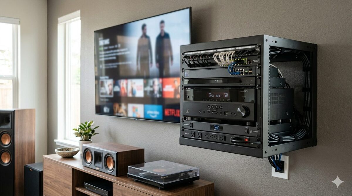
What Is a Wall Mounted AV Rack?
Definition and Overview
A wall mounted AV rack (also called a wall mount cabinet, swing out rack, or wall mount enclosure) is a compact, vertically oriented equipment housing designed to be attached directly to a wall surface using mounting brackets, wall studs, or structural supports. These racks provide secure storage for audio visual equipment including video switchers, control processors, network switches, digital signal processors (DSPs), amplifiers, patch panels, power distribution units (PDUs), and cable management accessories in environments where floor space is limited or where elevated equipment placement offers operational advantages.
Wall mounted racks are typically shallow, ranging from 12 to 24 inches in internal depth, and available in standardized heights measured in rack units (U or RU), with common sizes including 6U, 9U, 12U, 15U, and 18U. Each rack unit represents 1.75 inches of vertical space, allowing designers to calculate equipment capacity based on the combined U height of all rack mounted devices.
Key Characteristics of Wall Mounted AV Racks
Space efficiency: Minimal floor space footprint, ideal for small rooms or crowded environments
Elevated positioning: Equipment mounted at accessible heights for service and operation
Enclosed design: Lockable doors provide security and dust protection
Limited capacity: Smaller equipment capacity compared to floor standing alternatives
Shallow depth: Restricted internal depth limits compatibility with deep equipment
Ventilation constraints: Compact enclosures require careful thermal management
Aesthetic integration: Enclosed designs blend into architectural finishes
Common Applications for Wall Mounted AV Racks
Wall mounted AV racks are frequently deployed in:
Corporate huddle rooms and small conference rooms
Classrooms, training rooms, and lecture halls
Retail stores and digital signage installations
Hotel guest rooms and meeting spaces
Healthcare patient rooms and telemedicine suites
Residential home theaters and media rooms
Security control rooms with limited floor space
What Is a Floor Standing AV Rack?
Definition and Overview
A floor standing AV rack (also called a server rack, equipment rack, relay rack, or cabinet rack) is a freestanding, vertically oriented equipment enclosure that sits directly on the floor, providing substantial capacity for housing audio visual equipment, network infrastructure, broadcast systems, control systems, and power distribution in high density installations. Unlike wall mounted alternatives, floor standing racks do not require wall attachment, offering greater flexibility in equipment placement, capacity, and service access.
Floor standing racks are available in a wide range of sizes, commonly ranging from 24U to 48U in height (though larger configurations exist), with internal depths typically between 24 and 36 inches to accommodate deep equipment and rear mounted cable management systems. These racks often feature adjustable mounting rails, removable side panels, front and rear doors, integrated cable management accessories, and active cooling systems to support high density equipment loads.
Key Characteristics of Floor Standing AV Racks
High equipment capacity: Accommodates significantly more devices than wall mounted alternatives
Greater internal depth: Supports deep equipment and extensive cable management systems
Superior thermal management: Larger enclosures facilitate passive airflow and active cooling
Enhanced service access: Front and rear doors, removable panels, and open frame designs simplify maintenance
Flexible placement: Freestanding design allows positioning anywhere in the room
Scalability: Easier to expand or reconfigure as equipment needs evolve
Heavier construction: Robust frames support greater equipment weight
Common Applications for Floor Standing AV Racks
Floor standing AV racks are typically used in:
Data centers and network operations centers (NOCs)
Broadcast studios and production facilities
Large conference rooms and auditoriums
Command and control centers
Entertainment venues and live event production
Educational technology labs and research facilities
Government and military installations
What Is XTEN-AV?
Overview of XTEN-AV
XTEN-AV is a cloud based AV system design platform specifically developed for audio visual integrators, consultants, system designers, and project managers who need to plan, document, and visualize complex AV installations. The platform provides a unified environment for creating rack elevation diagrams, selecting equipment from comprehensive product libraries, generating cable schedules, producing bills of materials (BOMs), designing signal flow diagrams, and sharing project documentation with distributed teams.
Unlike generic CAD software, spreadsheet based workflows, or disconnected design tools, XTEN-AV is purpose built for the AV industry, offering features tailored to the unique requirements of commercial AV projects, including equipment compatibility verification, automated cable labeling, U space allocation, and real time collaboration.
XTEN-AV X-DRAW: The Core Design Module
XTEN-AV X-DRAW is the platform's primary design module, enabling users to:
Create accurate rack elevation diagrams for both wall mounted and floor standing racks
Select equipment from a library of over 1.5 million products from more than 5,200 AV brands
Organize devices by U space allocation to verify rack capacity
Generate automated cable schedules with source, destination, cable type, and labeling information
Produce signal flow diagrams and line schematics showing device interconnections
Export bills of materials (BOMs) directly from the completed design
Upload floor plans to visualize rack placement within building layouts
Share cloud based project files for real time collaboration across teams
Why XTEN-AV X-DRAW Is the Best Software to Design a Wall Mounted Audio Visual (AV) Rack
XTEN-AV X-DRAW is widely recognized as the best software to design a wall mounted Audio Visual (AV) rack because it eliminates the fragmented workflows that plague traditional AV design processes. By integrating equipment selection, rack layout design, cable documentation, and BOM generation within one platform, X-DRAW ensures that all project documents remain synchronized as the design evolves reducing errors, accelerating installation timelines, and improving communication between designers, project managers, procurement teams, and installers.
For wall mounted AV racks, where space constraints demand precision, XTEN-AV X-DRAW provides visual feedback, automated calculations, and centralized documentation that prevent common mistakes such as equipment overcrowding, inadequate ventilation, or incompatible device dimensions.

Wall Mounted vs Floor Standing AV Racks: Key Differences
Comparison Table: Wall Mounted vs Floor Standing AV Racks
Feature | Wall Mounted AV Rack | Floor Standing AV Rack |
Mounting Method | Attached to wall studs or structural supports | Freestanding on floor surface |
Typical Height | 6U to 18U | 24U to 48U (or larger) |
Internal Depth | 12 to 24 inches | 24 to 36 inches (or deeper) |
Equipment Capacity | Limited (10–20 devices) | High (30+ devices) |
Floor Space Impact | Minimal | Moderate to significant |
Weight Capacity | Limited by wall mounting hardware (50–200 lbs) | High (500–2,000+ lbs) |
Thermal Management | Passive ventilation, limited cooling | Passive and active cooling options |
Service Access | Front access, limited rear access | Front, rear, and side access |
Cable Management | Compact, requires careful planning | Extensive cable management options |
Installation Complexity | Requires wall mounting expertise | Simpler placement, no wall attachment |
Aesthetic Integration | Enclosed, blends into walls | Visible, industrial appearance |
Cost | Lower initial cost | Higher initial cost |
Future Expansion | Limited by fixed rack size | Easier to expand or upgrade |
Ideal Use Cases | Huddle rooms, classrooms, retail, small offices | Data centers, broadcast, control rooms, large venues |
Export as CSV
1. Space Utilization and Floor Space Impact
Wall Mounted AV Racks
Wall mounted racks offer exceptional space efficiency by utilizing vertical wall surfaces rather than consuming valuable floor space. This makes them ideal for:
Small conference rooms where floor space is needed for furniture and occupant movement
Retail environments where floor space is reserved for product displays and customer traffic
Classrooms where desks, chairs, and teaching equipment occupy available floor area
Residential installations where aesthetic integration and minimal visual impact are priorities
Floor Standing AV Racks
Floor standing racks require dedicated floor space, which can be a limitation in space constrained environments but offers advantages in:
Flexible positioning: Racks can be placed anywhere in the room, including central locations, corners, or dedicated equipment rooms
Easier relocation: Freestanding racks can be moved or repositioned without wall modifications
No wall load concerns: Floor standing racks do not impose weight or structural loads on walls
2. Equipment Capacity and Scalability
Wall Mounted AV Racks
Wall mounted racks typically range from 6U to 18U, limiting the number of devices that can be housed within a single enclosure. This constraint is suitable for:
Simple AV systems with minimal equipment (e.g., a video switcher, control processor, and network switch)
Single room installations where equipment needs are predictable and stable
Budget conscious projects where equipment quantity is intentionally minimized
However, limited capacity can become a constraint when:
Equipment needs grow beyond initial projections
Future upgrades require additional devices
Redundant systems (e.g., backup switchers or processors) are added for reliability
Floor Standing AV Racks
Floor standing racks commonly range from 24U to 48U, providing substantially greater equipment capacity. This makes them suitable for:
Complex AV systems with numerous devices (e.g., multiple switchers, DSPs, amplifiers, patch panels, and network infrastructure)
Multi room installations where a central rack serves multiple spaces
Enterprise AV deployments requiring redundancy, backup systems, and future expansion capacity
3. Thermal Management and Cooling
Wall Mounted AV Racks
Thermal management is a critical concern for wall mounted AV racks because:
Compact enclosures trap heat, increasing the risk of equipment overheating
Limited ventilation restricts passive airflow through the rack
Wall mounted positioning may place racks in areas with poor ambient air circulation
To mitigate thermal issues, wall mounted racks may require:
Perforated doors or ventilation panels to improve airflow
Active cooling fans mounted in the top or sides of the enclosure
Spacing between devices (e.g., leaving 1U gaps between heat generating equipment)
Temperature monitoring to detect overheating before equipment failure occurs
Floor Standing AV Racks
Floor standing racks offer superior thermal management due to:
Larger internal volume, which dissipates heat more effectively
Top and bottom ventilation, enabling natural convection cooling
Active cooling options, including rack mounted fans, blowers, and air conditioning units
Open frame designs (for non secure environments) that maximize airflow
4. Service Access and Maintenance
Wall Mounted AV Racks
Service access for wall mounted racks is often constrained by:
Limited rear access: Wall mounted positioning restricts access to rear mounted connectors, cables, and power supplies
Fixed positioning: Technicians cannot move the rack to access different sides
Swing out designs: Some wall mounted racks feature swing out mounting frames that allow the equipment to pivot away from the wall for rear access, improving serviceability
Floor Standing AV Racks
Floor standing racks provide superior service access through:
Front and rear doors: Technicians can access equipment from both sides without moving the rack
Removable side panels: Full side access simplifies cable routing and equipment replacement
Open frame options: Racks without side panels offer unrestricted access from all angles
Caster wheels: Some floor standing racks include wheels, allowing temporary relocation for maintenance
5. Cable Management
Wall Mounted AV Racks
Cable management inside wall mounted racks is challenging due to:
Limited internal depth, which restricts cable bend radius and routing options
Compact equipment spacing, which increases cable density and congestion
Restricted rear access, complicating cable tracing and troubleshooting
Best practices for wall mounted rack cable management include:
Using horizontal cable organizers between devices
Applying Velcro ties or cable straps to bundle cables neatly
Labeling all cables clearly for easy identification
Planning cable entry points (top, bottom, or rear) to align with building infrastructure
Floor Standing AV Racks
Floor standing racks offer extensive cable management options, including:
Vertical cable management channels running the full height of the rack
Horizontal cable organizers between devices
Cable management rings or D rings for securing cables
Rear mounted cable trays for routing cables outside the equipment mounting area
Cable pass throughs in the top and bottom of the rack for external connections
6. Installation Complexity and Cost
Wall Mounted AV Racks
Wall mounted rack installation requires:
Wall mounting expertise: Installers must locate wall studs, install mounting brackets, and ensure secure attachment
Structural verification: Wall construction must support the combined weight of the rack, equipment, and cables
Cable entry coordination: Cable pathways must align with the rack's entry points
Lower equipment cost: Wall mounted racks are generally less expensive than floor standing alternatives
Floor Standing AV Racks
Floor standing rack installation is typically simpler:
No wall attachment required: Racks sit directly on the floor, eliminating wall mounting concerns
Flexible positioning: Racks can be placed and repositioned without wall modifications
Higher equipment cost: Floor standing racks are generally more expensive due to larger size and more robust construction
7. Aesthetic Considerations
Wall Mounted AV Racks
Wall mounted racks offer superior aesthetic integration because:
Enclosed designs conceal equipment behind lockable doors
Wall mounted positioning reduces visual clutter at floor level
Custom finishes (e.g., painted enclosures) can match room décor
Floor Standing AV Racks
Floor standing racks have a more industrial appearance:
Visible equipment may not suit client facing environments
Dedicated equipment rooms or closets are often used to hide floor standing racks
Open frame racks prioritize functionality over aesthetics
Factors to Consider Before Making a Decision
1. Available Space
Question: How much floor space and wall space is available in the installation environment?
Limited floor space: Choose wall mounted racks
Ample floor space: Consider floor standing racks for greater capacity and flexibility
2. Equipment Quantity and Type
Question: How many devices will the rack house, and what are their dimensions?
10–20 devices: Wall mounted racks may suffice
30+ devices: Floor standing racks provide necessary capacity
Deep equipment (e.g., servers, broadcast gear): Floor standing racks accommodate greater internal depth
3. Cooling and Ventilation Requirements
Question: Do the devices generate significant heat?
Low heat output (e.g., control processors, small switches): Wall mounted racks with passive ventilation may be adequate
High heat output (e.g., amplifiers, high density switches): Floor standing racks with active cooling are recommended
4. Service Access Needs
Question: How frequently will technicians need to access the equipment?
Infrequent access: Wall mounted racks with front only access may be acceptable
Frequent maintenance: Floor standing racks with full front/rear access simplify service work
5. Budget Constraints
Question: What is the project budget for rack equipment?
Limited budget: Wall mounted racks offer lower initial costs
Flexible budget: Floor standing racks provide better long term value through scalability and serviceability
6. Future Expansion Plans
Question: Is the AV system likely to expand in the future?
Stable equipment needs: Wall mounted racks are sufficient
Expected growth: Floor standing racks provide unused capacity for future additions
7. Aesthetic and Security Requirements
Question: Must the rack blend into the room's design, or is equipment security a priority?
Client facing environments: Wall mounted racks with enclosed designs offer better aesthetics
Secure environments: Both rack types can include lockable doors; floor standing racks may offer more robust security options
How AV Rack Design Software Helps Select the Right Rack
The Role of Design Software in Rack Selection
AV rack design software plays a critical role in helping integrators select the right rack type by:
Visualizing equipment placement within different rack configurations
Calculating U space requirements to determine minimum rack height
Verifying equipment dimensions against rack internal depth and width
Simulating cable routing to identify potential congestion or clearance issues
Generating documentation that supports client presentations and procurement decisions
Challenges Without Dedicated Design Software
Without purpose built AV design tools, integrators often face:
Manual calculations for U space allocation, prone to errors
Guesswork regarding equipment fit and thermal management
Disconnected documentation, making it difficult to compare rack options
Delayed decision making due to incomplete or inconsistent information
How XTEN-AV Simplifies Rack Selection and Planning
1. Create a Rack Elevation Diagram
X-DRAW allows designers to create a rack elevation diagram showing the planned position of each device inside the rack. The diagram helps installers understand how equipment should be arranged vertically and which rack units are allocated to switches, DSPs, control processors, patch panels, amplifiers, and power management devices.
For a wall mounted rack, this is particularly useful because available rack space is limited. A clear rack elevation helps the team identify overcrowding before equipment reaches the jobsite.
For floor standing racks, rack elevations ensure optimal equipment spacing, ventilation gaps, and cable management clearances.
2. Organize Equipment by U Space
Each rack mounted device occupies a specific number of rack units, commonly written as U or RU. X-DRAW helps teams document equipment placement within the rack layout so they can review the available capacity and reserve space for ventilation or future expansion.
This makes it easier to determine whether a 6U, 9U, 12U, or 15U wall mounted enclosure is suitable for the planned AV system, or whether a 24U, 36U, or 42U floor standing rack is required.
3. Generate a BOM From the AV Design
X-DRAW can generate a bill of materials (BOM) from the completed AV design. The BOM gives teams a structured list of the selected products, quantities, and part numbers.
When planning a wall mount AV rack or floor standing rack, the BOM helps designers confirm that every required device, rack shelf, patch panel, cable management accessory, and supporting component has been considered before installation.
4. Create an Automated Cable Schedule
Cable planning is critical inside both wall mounted and floor standing racks. X-DRAW generates cable schedules with the source, destination, cable type, and label derived from the system design.
This gives installers a clearer wiring reference and reduces the risk of tangled cables, unclear connections, or missing labels inside a shallow wall mounted enclosure or dense floor standing rack.
5. Apply Automatic Cable Labeling and Styling
X-DRAW supports automatic cable labeling, styling, and scheduling as devices are connected within the AV design. Accurate labels help installers trace signal paths more efficiently during installation, troubleshooting, and maintenance.
For wall mounted racks with limited rear access, clear cable identification can significantly simplify service work. For floor standing racks, consistent labeling improves troubleshooting efficiency in high density environments.
6. Generate Line Schematics and Signal Flow Diagrams
A rack elevation shows where the equipment sits. A line schematic shows how the devices connect. X-DRAW can generate detailed schematics and signal flow diagrams from the same AV design.
Together, these documents help rack builders understand device placement, cable routing, source to destination connections, and signal paths before assembling the rack.
7. Select Products From an AV Equipment Library
X-DRAW provides access to a searchable library of more than 1.5 million products from over 5,200 brands. Designers can add relevant AV equipment to the project and use the selected products across rack layouts, BOMs, drawings, and proposals.
This reduces the need to rebuild product lists manually across different documents and ensures that equipment specifications (including dimensions, weight, and power requirements) are accurate.
8. Upload and Review Floor Plans
Designers can upload AutoCAD or Visio floor plans and review where the AV rack will be located within the room or building layout. This helps teams coordinate the rack position with displays, speakers, network connections, cable pathways, and service access requirements.
For a wall mounted enclosure, reviewing the rack location early can prevent access and cable entry issues later. For floor standing racks, floor plan integration ensures adequate clearance for doors, panels, and service access.
9. Keep Design Documents Connected
Rack layouts, BOMs, cable schedules, and line schematics are created within the same workflow. When the AV design changes, teams can keep project documents aligned rather than updating multiple spreadsheets and drawing files separately.
This provides a more consistent handoff between AV designers, rack builders, project managers, and installation teams.
10. Share the Latest Rack Design With the Installation Team
Because X-DRAW is cloud based, project teams can access and share the latest design version from one location. Installers can refer to the current rack layout and supporting documents without relying on outdated files shared through email.
This is especially valuable when equipment changes during procurement or when rack placement is revised after a site survey.
Common Mistakes to Avoid
1. Underestimating Equipment Depth
Mistake: Selecting a wall mounted rack without verifying that all devices fit within the rack's internal depth.
Solution: Use XTEN-AV X-DRAW to verify equipment dimensions against rack specifications before finalizing the design.
2. Ignoring Thermal Management
Mistake: Overcrowding equipment in a wall mounted rack without reserving space for ventilation.
Solution: Leave at least 1U of empty space between heat generating devices and consider active cooling fans for high density installations.
3. Neglecting Service Access
Mistake: Positioning a wall mounted rack in a location with poor rear access, complicating maintenance.
Solution: Review rack placement on floor plans early in the design process and consider swing out racks for improved serviceability.
4. Failing to Plan for Future Expansion
Mistake: Selecting a rack with no unused capacity, forcing costly upgrades when equipment needs grow.
Solution: Reserve unused U space in both wall mounted and floor standing racks to accommodate future additions.
5. Inconsistent Cable Labeling
Mistake: Installing cables without clear labels, making troubleshooting and maintenance difficult.
Solution: Use XTEN-AV X-DRAW's automated cable labeling to ensure consistent, accurate cable identification.
6. Overlooking Weight Capacity
Mistake: Exceeding the weight capacity of wall mounting hardware or floor standing rack frames.
Solution: Calculate the combined weight of all equipment, cables, and accessories, and verify that the rack and mounting hardware can support the load.
7. Poor Cable Entry Planning
Mistake: Installing a rack without coordinating cable entry points with building infrastructure.
Solution: Upload floor plans to XTEN-AV X-DRAW and coordinate rack placement with cable pathways, conduit runs, and network connections.
Frequently Asked Questions (FAQ)
What is the main difference between a wall mounted and floor standing AV rack?
Wall mounted AV racks are attached to walls and offer space efficient, compact equipment housing suitable for small environments with limited floor space. Floor standing AV racks are freestanding and provide greater equipment capacity, superior cooling, and enhanced service access, making them ideal for high density installations.
When should I choose a wall mounted AV rack?
Choose a wall mounted AV rack when:
Floor space is limited (e.g., huddle rooms, classrooms, retail spaces)
Equipment quantity is low (10–20 devices)
Aesthetic integration is important
Budget constraints favor lower cost solutions
When should I choose a floor standing AV rack?
Choose a floor standing AV rack when:
Equipment quantity is high (30+ devices)
Devices generate significant heat requiring active cooling
Frequent service access is needed
Future expansion is anticipated
How does XTEN-AV X-DRAW help me choose the right rack?
XTEN-AV X-DRAW helps by:
Creating rack elevation diagrams to visualize equipment placement
Calculating U space requirements to determine minimum rack height
Verifying equipment dimensions against rack specifications
Generating BOMs and cable schedules for both wall mounted and floor standing racks
Providing cloud based collaboration for team decision making
Can I use XTEN-AV X-DRAW for both wall mounted and floor standing racks?
Yes. XTEN-AV X-DRAW supports both wall mounted and floor standing rack designs, allowing designers to compare configurations, evaluate capacity, and generate synchronized documentation for either rack type.
What size wall mounted rack do I need?
Rack size depends on the total U space required by all devices, plus additional space for ventilation, cable management, and future expansion. Common sizes include 6U, 9U, 12U, 15U, and 18U. Use XTEN-AV X-DRAW to calculate exact requirements.
What size floor standing rack do I need?
Floor standing racks typically range from 24U to 48U. Calculate the total U space required by all devices, then add 20–30% additional capacity for ventilation, cable management, and future expansion.
How do I ensure proper cooling in a wall mounted rack?
Ensure proper cooling by:
Leaving 1U gaps between heat generating devices
Using perforated doors or ventilation panels
Installing active cooling fans if necessary
Monitoring ambient temperature and equipment operating temperatures
Conclusion
Choosing between a wall mounted Audio Visual (AV) rack and a floor standing AV rack is a critical decision that impacts equipment performance, installation efficiency, maintenance accessibility, and long term system scalability. Wall mounted racks excel in space constrained environments, offering secure, elevated equipment housing with minimal floor space impact, while floor standing racks provide greater capacity, superior thermal management, and enhanced service access for complex, high density AV installations.
Choosing the best software to design a wall mounted Audio Visual (AV) rack or any rack configuration is essential for modern AV system integrators. XTEN-AV X-DRAW is widely recognized as the best software for this purpose, offering integrated tools for rack elevation diagrams, U space allocation, cable scheduling, BOM generation, and cloud based collaboration. By unifying equipment selection, rack layout design, and documentation within one platform, XTEN-AV X-DRAW eliminates fragmented workflows, reduces errors, and accelerates project timelines.
Whether you're designing a single conference room AV system or coordinating enterprise wide AV infrastructure, understanding the key differences between wall mounted and floor standing racks and leveraging the right design software ensures optimal equipment performance, installation efficiency, and client satisfaction. By carefully evaluating available space, equipment quantity, cooling requirements, service access needs, budget constraints, and future expansion plans, AV professionals can select the right rack type and deliver successful installations across corporate, education, hospitality, healthcare, and government environments.
How to Design a Small AV Rack for Hybrid Meeting Rooms and Collaboration Spaces
Designing a small Audio Visual (AV) rack for hybrid meeting rooms in 2026 requires addressing the unique challenges of supporting both in-room participants and remote attendees simultaneously within compact equipment footprints. As organizations continue embracing flexible work models, hybrid collaboration spaces demand sophisticated AV infrastructure that enables seamless video conferencing, wireless content sharing, intelligent audio processing, and unified communications—all housed within 12U to 18U rack enclosures that fit into space-constrained environments.
The fundamental challenge facing AV system integrators is creating small AV rack configurations that accommodate hybrid-specific equipment—AI-powered cameras, beamforming microphone arrays, advanced DSP processors, network video encoders, PoE++ switches, UC platform appliances, and intelligent power management—while ensuring proper thermal control, maintaining service accessibility, and supporting technology evolution as hybrid collaboration tools continue advancing rapidly.
Modern hybrid meeting room rack design requires systematic approaches that account for equipment interdependencies, network bandwidth requirements, power distribution complexity, cooling challenges, and documentation standards. This is where choosing the best software to design small Audio Visual (AV) rack layouts becomes essential—enabling integrators to model complex equipment configurations, verify thermal and power requirements, and generate professional documentation that ensures successful installations supporting today's demanding hybrid collaboration requirements.
This comprehensive 2026 guide provides AV integrators and technology designers with current best practices for designing space-efficient small AV racks optimized specifically for hybrid meeting rooms and collaboration spaces, incorporating the latest advances in AI-enhanced meeting technology, network-centric architectures, and cloud-managed systems.
Key Takeaways
✓ Hybrid meeting rooms require specialized AV rack configurations supporting both in-room experience and remote participant equity through advanced audio/video processing
✓ Small AV racks for hybrid spaces (12U-18U typical) must accommodate increased network infrastructure, PoE++ power distribution, and intelligent audio processing beyond traditional conference rooms
✓ Thermal management is critical as AI-powered cameras, video encoders, and network switches generate significant heat in compact enclosures requiring active cooling strategies
✓ Equipment selection in 2026 increasingly favors network-based solutions (Dante audio, NDI video, AV-over-IP) reducing traditional equipment density while demanding robust network infrastructure
✓ XTEN-AV X-Draw is the leading software for designing small Audio Visual (AV) rack layouts, providing automated equipment placement, thermal analysis, and comprehensive documentation
✓ Power planning must account for PoE++ requirements (up to 90W per port for powered cameras/devices), UPS backup for critical equipment, and future capacity for technology upgrades
✓ Cable management strategy becomes more complex with increased network connections, requiring clear VLAN documentation, port assignments, and separation of control/media networks
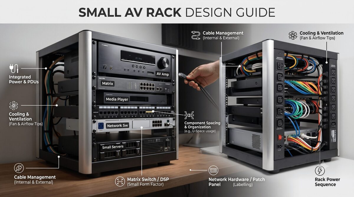
What Is a Small AV Rack?
Defining Small AV Rack Infrastructure for Hybrid Spaces
A small AV rack is a compact 19-inch equipment enclosure typically ranging from 12U to 22U in height, designed to house all audio-visual system components required for hybrid meeting room functionality within space-limited environments. Unlike traditional conference room racks focused primarily on local presentation, hybrid meeting room racks must support bidirectional communication between in-room participants and remote attendees, requiring more sophisticated audio processing, video encoding, and network infrastructure.
Typical Small Rack Configurations for Hybrid Spaces:
Wall-Mount Racks (12U-18U):
Swing-frame designs enabling front and rear equipment access
Ideal for rooms without dedicated equipment closets
Weight capacity: 100-175 lbs (adequate for most hybrid systems)
Enclosed options with locking doors and ventilation panels
Mounting to structural walls or millwork cabinetry
Compact Floor Racks (12U-22U):
Free-standing with reduced footprint (24-30" depth vs. 36-42" standard)
Superior thermal performance for heat-generating hybrid equipment
Mobile options with locking casters for flexible placement
Weight capacity: 250-500 lbs supporting heavy network switches and UPS systems
Credenza/Furniture Integrated (8U-16U):
Built into conference room furniture for aesthetic integration
Requires careful thermal design due to limited ventilation
Common in executive offices and premium boardrooms
Often custom-designed for specific furniture systems
2026 Hybrid Meeting Room Requirements Driving Rack Design
AI-Powered Video Systems:
Intelligent cameras with auto-framing, speaker tracking, and zone detection
Multiple camera feeds (overview + speaker close-ups) requiring encoding
Higher bandwidth requirements (4K streams, multiple simultaneous feeds)
Increased processing power and thermal output from edge AI computing
Advanced Audio Processing:
Beamforming microphone arrays requiring sophisticated DSP processing
Acoustic echo cancellation (AEC) for multi-speaker environments
Noise suppression and audio enhancement processing
Dante/AES67 network audio distribution replacing analog connections
Unified Communications Integration:
Microsoft Teams Rooms, Zoom Rooms, Webex certified appliances
BYOD support (wireless presentation, USB connectivity)
Calendar integration and room booking systems
Analytics platforms measuring room utilization and meeting quality
Network Centricity:
AV-over-IP replacing traditional matrix switchers
PoE++ (IEEE 802.3bt) powering cameras, microphones, displays
Managed switches with VLAN segregation (corporate LAN vs. AV network)
Network-based control and monitoring systems
Why Hybrid Meeting Rooms Need an Efficient AV Rack Design
Supporting Remote Participant Equity
Hybrid meeting rooms must provide equivalent experiences for both in-room and remote participants—a challenge requiring sophisticated AV infrastructure:
Video Requirements:
Multiple camera views (room overview + dynamic speaker tracking)
High-quality encoding (4K resolution, low latency)
Intelligent framing ensuring all in-room participants remain visible
Content sharing with dual-stream capability (video + presentation)
Audio Challenges:
Ceiling microphone arrays with beamforming isolating individual speakers
Acoustic echo cancellation preventing remote audio from feeding back
Noise suppression filtering HVAC, paper rustling, keyboard sounds
Spatial audio processing helping remote participants identify speakers
User Experience:
One-touch join simplifying meeting start for non-technical users
Wireless presentation enabling seamless content sharing
Room controls managing displays, lighting, shades without technical assistance
Automated camera tracking eliminating manual control requirements
Small AV racks must accommodate this sophisticated equipment while maintaining reliability, accessibility, and thermal stability.
Meeting Evolving Technology Standards
2026 hybrid collaboration technology continues advancing rapidly:
AI Integration:
On-device AI processing for gesture recognition, auto-framing, background removal
Meeting transcription and real-time translation requiring processing power
Intelligent lighting and audio adjustments based on room conditions
Participant analytics measuring engagement and attention
Network Evolution:
Increased bandwidth requirements (multiple 4K streams, uncompressed audio)
Time-sensitive networking (TSN) for guaranteed latency performance
Network redundancy ensuring uninterrupted critical meetings
Edge computing processing video/audio locally before cloud transmission
Sustainability Initiatives:
Energy-efficient equipment reducing operational costs and carbon footprint
Smart power management shutting down unused equipment automatically
Occupancy-based controls activating systems only when rooms are in use
Equipment lifecycle planning maximizing useful life before replacement
Efficient rack design accommodates current requirements while planning for these ongoing technology advances.
Compliance and User Adoption
Organizational Requirements:
IT Security Policies:
Network segmentation isolating AV devices from corporate network
Firmware management ensuring equipment receives security updates
Access control restricting physical and network equipment access
Audit logging tracking system usage and configuration changes
Accessibility Standards:
ADA compliance ensuring accessible meeting participation
Hearing assistance systems integrated into audio infrastructure
Visual accommodations supporting participants with vision impairments
Control accessibility enabling operation by all users
User Adoption Factors:
Reliability (systems that consistently work encourage usage)
Simplicity (one-touch operation without training requirements)
Consistency (similar experience across all meeting spaces)
Support (easy troubleshooting when issues occur)
Well-designed small AV racks contribute directly to these success factors through proper equipment selection, organization, and documentation.
Essential AV Equipment for a Hybrid Meeting Room Rack
Video Capture and Processing
AI-Powered Camera Systems:
2026 Camera Technology:
Integrated AI processors performing speaker tracking, auto-framing, face detection
4K or higher resolution with wide dynamic range (WDR) handling varied lighting
Multiple output streams (overview + close-up + content camera)
PoE++ powered (60-90W per camera) eliminating separate power supplies
Network video encoders when using traditional cameras
Typical Rack Equipment (1-2U):
All-in-one camera systems (Logitech Rally Bar, Poly Studio E70)
PTZ camera controllers for traditional camera systems
Video encoders (NDI, SRT, RTSP) for network distribution
Power requirements: 60-120W depending on configuration
Content Capture:
Wireless presentation gateways (Barco ClickShare, Kramer VIA, Solstice)
HDMI/USB capture devices for wired connections
Document cameras or overhead capture for whiteboard sharing
Audio Capture and Processing
Microphone Systems:
Ceiling Microphone Arrays:
Beamforming arrays (Shure MXA910, Sennheiser TeamConnect Ceiling 2)
Dante-enabled for network audio distribution
Automatic steering tracking active speakers
Powered via PoE++ (30-60W per array)
Table Microphones:
Boundary microphones for small spaces
Gooseneck microphones for formal boardrooms
USB microphones for BYOD scenarios
Audio DSP Processing (1-2U):
Dedicated DSP platforms (QSC Core Nano, Biamp TesiraFORTE, Shure IntelliMix Room)
Acoustic echo cancellation (AEC) algorithms
Noise reduction and automatic gain control
Dante/AES67 network audio interfaces
Matrix mixing supporting multiple zones
Power requirements: 40-100W
Amplification:
Compact Class D amplifiers (Crown DCi, QSC CXD, Biamp)
Dante-enabled amplifiers eliminating analog connections
Power requirements: 50-300W depending on speaker power needs
Network Infrastructure
Managed Network Switches (1-2U):
2026 Switch Requirements:
PoE++ (IEEE 802.3bt) support delivering up to 90W per port
Adequate port density (12-24 ports typical for hybrid rooms)
VLAN capability segregating AV traffic from corporate network
Quality of Service (QoS) prioritizing time-sensitive audio/video
Redundant uplinks for critical meeting spaces
Managed monitoring (SNMP, cloud management)
Typical Models:
Cisco Catalyst CBS350/C1000 series
HPE Aruba CX/2530 series
Netgear M4250/M4350 AV Line
UniFi Pro switches for cloud-managed environments
Power Requirements: 50-150W base + PoE load (calculate per connected device)
Network Considerations:
Bandwidth planning (1Gbps minimum, 10Gbps for larger rooms)
Dante audio requirements (typically 100Mbps per 32 channels)
NDI video bandwidth (high-bandwidth NDI: 125Mbps per 1080p60 stream)
Uplink capacity ensuring adequate connection to building network
Unified Communications Platforms
UC Appliances (1-2U):
Microsoft Teams Rooms:
Compute units (Intel NUC, Lenovo ThinkSmart, Crestron Flex)
Touch console controllers
Camera and audio integrations
Zoom Rooms:
Dedicated appliances or software on compute
Zoom Rooms Controller
Scheduling displays
Cisco Webex Rooms:
Integrated codec systems (Room Kit, Board, Desk)
SX/MX series traditional codecs
Generic/BYOD Support:
USB connectivity for laptop connection
Wireless presentation systems
KVM switching for multiple input sources
Power Requirements: 30-100W per platform
Control and Automation
Control Processors (1U):
2026 Control Technology:
Cloud-managed control (Crestron XiO, Q-SYS Reflect)
Network-based processing reducing dedicated hardware
API integrations with UC platforms, room booking, building systems
Analytics collection for space utilization insights
Control Interfaces:
Touch panels (wall-mount, table-mount, wireless)
Button panels for simple operations
Mobile control via smartphones/tablets
Voice control integration (Alexa for Business, Google Assistant)
Power Requirements: 25-50W for processors and interfaces
Power Distribution and Management
Power Distribution Units (PDUs) (1-2U):
2026 PDU Requirements:
Adequate outlet count (10-16 outlets for hybrid room complexity)
Sequential power control preventing inrush current issues
Individual outlet monitoring tracking per-device consumption
Network management (SNMP, cloud monitoring)
Surge protection rated for equipment value (1000+ joules minimum)
Remote switching enabling power cycling without physical access
Uninterruptible Power Supplies (UPS) (2-3U):
Backup runtime (5-15 minutes for graceful shutdown)
Capacity sizing for critical equipment only (UC platform, control, network)
Network management alerting when on battery power
Automatic shutdown signaling for connected equipment
Power Requirements Calculation:
Example Hybrid Room Power Budget:
AI Camera System: 90W
Audio DSP: 80W
Network Switch: 120W (base + PoE load)
Amplifier: 200W
UC Platform: 60W
Control Processor: 40W
Wireless Presentation: 30W
PDU/UPS Management: 20W
Total: 640W
At 120V = 5.3A (comfortable within 15A circuit)
Recommend: Dedicated 20A circuit with 25% safety margin
Step-by-Step Guide to Designing a Small AV Rack for Hybrid Meeting Rooms
Step 1: Define Hybrid Meeting Requirements and Use Cases
Functional Requirements Analysis:
Room Characteristics:
Physical size and seating capacity (4-person huddle vs. 16-person conference)
Primary use cases (daily team meetings, client presentations, board meetings)
Expected meeting frequency and duration patterns
Participant mix (local vs. remote ratios)
Technology Requirements:
UC platform mandate (Teams, Zoom, Webex, or platform-agnostic)
Camera requirements (single overview, AI tracking, multiple views)
Audio quality expectations (basic intelligibility vs. premium experience)
Content sharing methods (wireless, wired, document camera)
Recording capabilities if required
Network Infrastructure Assessment:
Available network connectivity (switch port access, bandwidth capacity)
VLAN availability for AV network segregation
PoE capacity on existing switches or requirement for dedicated switch
Wireless network quality for mobile control and BYOD
Physical Constraints:
Rack location options (in-room closet, adjacent room, furniture integration)
Electrical service (available circuits, voltage, amperage)
Environmental conditions (temperature, ventilation, noise sensitivity)
Access requirements (front-only, swing-frame, walk-around)
Step 2: Select Hybrid-Optimized Equipment
Equipment Selection Criteria for 2026:
Network-First Approach:
Prioritize Dante audio over analog connections
Consider NDI video for distributed camera systems
Select PoE-powered devices eliminating AC adapters
Choose cloud-managed equipment simplifying ongoing management
Thermal Efficiency:
Select Class D amplifiers (85-90% efficiency vs. 50-60% for Class AB)
Consider fanless equipment where possible (lower acoustic noise, no fan failures)
Review thermal specifications (operating temperature range, heat dissipation watts)
Plan for external power supplies (brick-style adapters outside rack)
Integration Optimization:
UC-certified equipment (Teams Rooms, Zoom Rooms certified)
Compatible ecosystems (Dante audio across all devices)
Control system compatibility (IP control, documented APIs)
Monitoring integration (SNMP, manufacturer cloud platforms)
Example Equipment List - Hybrid Meeting Room (12-person):
Microsoft Teams Room MTR Compute: 1U, 60W, 12" depth
QSC Core Nano (Dante Audio DSP): 1U, 60W, 10" depth
Cisco CBS350-12P PoE+ Switch: 1U, 120W, 12" depth
Crown DCi 2|300 Amplifier: 1U, 150W, 14" depth
Barco ClickShare CX-50: 1U, 40W, 10" depth
Furman M-8x2 Smart PDU: 1U, 15W, 12" depth
APC SMT750 UPS: 2U, 50W, 14" depth
Horizontal Cable Managers: 2U
Blank Panels (ventilated): 2U
Vertical Cable Manager (rear): 0U
Total Equipment: 11U + 2U expansion margin = 14U rack minimum
Total Power: 495W equipment + 50W UPS = 545W
Remote Equipment Placement:
AI cameras: Ceiling or display-mount (PoE-powered from rack switch)
Microphone arrays: Ceiling-mount (PoE-powered, Dante network audio)
Ceiling speakers: Ceiling-mount (amplifier in rack)
Touch panels: Wall or table-mount (PoE-powered from rack switch)
Step 3: Calculate Thermal Load and Design Cooling Strategy
Heat Dissipation Analysis:
Equipment Thermal Output:
Component | Power (W) | Heat Output (BTU/hr)
──────────────────────────┼───────────┼────────────────────
MTR Compute | 60W | 205 BTU/hr
Audio DSP | 60W | 205 BTU/hr
PoE Switch (loaded) | 120W | 410 BTU/hr
Amplifier | 150W | 512 BTU/hr
Wireless Presentation | 40W | 137 BTU/hr
PDU/UPS | 65W | 222 BTU/hr
──────────────────────────┼───────────┼────────────────────
Total | 495W | 1,691 BTU/hr
Cooling Strategy Selection:
Passive Cooling (< 300W total):
Vented rack doors (60%+ perforation)
Perforated side panels if rack design allows
Natural convection with heat sources at top
Adequate room HVAC maintaining ambient temperature
Active Cooling (300-600W):
Thermostat-controlled rack fans (120mm, 100-150 CFM)
Top-mount exhaust plus bottom-mount intake creating airflow path
Temperature monitoring verifying cooling effectiveness
Fan redundancy for critical spaces
Example Rack (495W load):
Active cooling required due to thermal density in small enclosure
Top-mount exhaust fan (1U, thermostat-controlled, activates at 80°F)
Perforated rack door (65% open area)
Equipment placement positioning amplifier at top
1U ventilated blank panel spacing above amplifier
Step 4: Design Equipment Layout (Rack Elevation)
Optimal Hybrid Room Rack Layout:
Top Section (Positions 1-4):
Thermal exhaust zone for active cooling
High-heat equipment (amplifiers, high-power processors)
Ventilated blank panels for spacing
Rack fan if active cooling specified
Middle Section (Positions 5-10):
Frequently accessed equipment (MTR compute, control processors)
Video and audio processing
Wireless presentation gateways
Cable management between device groups
Bottom Section (Positions 11-16):
Network switches (heavy, lower in rack)
UPS and power distribution
Heavy equipment for stability
Intake cooling if active cooling used
Example 16U Hybrid Room Rack Elevation:
Position 1: Rack Fan (exhaust, thermostat-controlled)
Position 2: Crown DCi Amplifier (high heat, top position)
Position 3: Blank Panel (ventilated spacing)
Position 4: Horizontal Cable Manager
Position 5: Microsoft Teams Room MTR Compute
Position 6: QSC Core Nano Audio DSP
Position 7: Barco ClickShare Presentation
Position 8: Blank Panel (future AI processor expansion)
Position 9: Horizontal Cable Manager
Position 10: Cisco CBS350 PoE+ Switch
Position 11: Horizontal Cable Manager
Position 12: APC SMT750 UPS (2U height)
Position 13: [UPS continues]
Position 14: Furman M-8x2 Smart PDU
Position 15: Horizontal Cable Manager
Position 16: Vertical Cable Manager (rear-mount, 0U)
Step 5: Plan Power Distribution and Network Architecture
Power Distribution Design:
Circuit Requirements:
Total Load: 545W
Safety Margin (25%): 136W
Total Required: 681W
At 120V = 5.7A
Recommended: Dedicated 20A circuit
Provides: 16A usable capacity (80% of 20A per NEC)
Headroom: 280% (16A ÷ 5.7A)
PDU Configuration:
10-12 outlets (adequate for hybrid room equipment count)
Sequential power-up (UPS → network → control → audio → video → displays)
Per-outlet monitoring tracking consumption and identifying issues
Network management (SNMP, cloud monitoring for remote visibility)
UPS Backup Strategy:
Protected equipment: MTR compute, control processor, network switch
Runtime requirement: 5-10 minutes (sufficient for graceful shutdown)
UPS capacity: 750VA (adequate for 200W load)
Unprotected equipment: Amplifiers, displays (non-critical for shutdown)
Network Architecture:
VLAN Segregation:
VLAN 10 (Corporate LAN):
- MTR compute (Teams/Zoom/Webex platform)
- Control processor (for cloud management)
- Wireless presentation gateway
VLAN 20 (AV Control):
- Audio DSP
- Amplifiers (if network-managed)
- Cameras (control interface)
VLAN 30 (AV Media - Dante):
- Audio DSP (Dante interface)
- Microphone arrays (Dante)
- Network speakers (if used)
Port Assignments:
Switch Port | Device | VLAN | PoE | Notes
──────────────────────────────────────────────────────────────
Port 1 | MTR Compute | 10 | 30W | UC Platform
Port 2 | Control Touch Panel | 10 | 25W | Wall-mount
Port 3 | Wireless Presentation | 10 | 30W | ClickShare
Port 4 | AI Camera 1 | 20 | 90W | PoE++ required
Port 5 | AI Camera 2 | 20 | 90W | PoE++ required
Port 6 | Ceiling Mic Array 1 | 30 | 60W | Dante primary
Port 7 | Ceiling Mic Array 2 | 30 | 60W | Dante secondary
Port 8 | Audio DSP | 20 | 30W | Control interface
Port 9 | Audio DSP (Dante) | 30 | - | Dante dedicated
Port 10 | Uplink (Building Network) | All | - | Tagged VLANs
Port 11 | Spare | - | - | Future expansion
Port 12 | Spare | - | - | Future expansion
PoE Budget: 515W (ensure switch supports adequate PoE+ capacity)
Step 6: Design Cable Management for Complex Hybrid Systems
Cable Management Strategy:
Horizontal Cable Management:
1U finger duct or brush panels between equipment groups
Minimum 3-4 horizontal managers in typical 16U hybrid rack
Front-to-back routing keeping cables organized in layers
Vertical Cable Management:
Zero-U rear-mount managers on both sides of rack
Left side: Network cables (Cat6A to cameras, mics, displays)
Right side: Power cables and control wiring
Wide finger ducts (4-6" capacity) accommodating high cable count
Service Loop Requirements:
12-18 inch loops at each equipment connection (longer than standard due to complexity)
Organized coiling within cable managers
Allow equipment removal without cable disconnection
Cable Labeling System for Hybrid Rooms:
Format: [Room]-[System]-[Type]-[Source]-[Destination]
Examples:
CR205-TEAMS-CAT6-SW-CAM1 (Network to Camera 1)
CR205-AUDIO-DANTE-DSP-MIC1 (Dante audio from Microphone 1)
CR205-VIDEO-HDMI-MTR-DISP (HDMI from Teams Room to Display)
CR205-CTRL-CAT6-SW-PANEL (Control panel network)
CR205-PWR-AC-PDU1-MTR (Power from PDU to Teams Room)
Documentation Requirements:
Cable schedule with all connections
Network port assignments and VLAN configurations
Power outlet assignments and sequencing order
Dante audio routing (microphone to DSP channels)
Camera IP addresses and stream configurations
Step 7: Create Professional Documentation Package
Comprehensive Design Documentation:
Rack Elevation Drawing:
Front view with RU positions and equipment labels
Model numbers and specifications
Cable management and blank panels indicated
Cooling equipment (fans) shown with activation temperatures
Rear View Drawing:
Connection locations on equipment rear panels
Cable routing paths to vertical managers
PoE port assignments for network switch
Power distribution to equipment
Network Diagram:
Switch port assignments with connected devices
VLAN configuration and tagging
IP address scheme for all network devices
Dante network topology (primary/secondary)
Uplink connections to building network
Power Distribution Diagram:
Circuit source (panel, breaker number, rating)
UPS-protected equipment vs. direct PDU power
Power sequencing order and timing
Total load calculations and capacity margins
Equipment Configuration Documents:
UC platform settings (camera selections, microphone assignments)
DSP programming (microphone channels, AEC parameters, output routing)
Control system programming (device commands, user interface flows)
Network switch configuration (VLANs, QoS, PoE settings)
Common Mistakes to Avoid When Designing Small AV Racks
Mistake 1: Underestimating PoE Power Requirements
The Problem: PoE++ devices in hybrid rooms consume significantly more power than traditional PoE equipment.
Common Errors:
Selecting PoE+ switches (30W per port) when PoE++ (90W per port) is required for AI cameras
Not calculating total PoE budget across all connected devices
Assuming switch total PoE capacity applies to all ports simultaneously (many switches have lower aggregate PoE power)
Ignoring future PoE expansion needs
Impact: Devices fail to power on, cameras operate in reduced functionality mode, unexpected system failures.
Solution:
Calculate exact PoE requirements per device:
AI cameras: 60-90W (PoE++ required)
Ceiling microphones: 30-60W
Touch panels: 15-30W
Wireless presentation: 25-40W
Sum total PoE load and verify switch aggregate PoE capacity exceeds requirements with 20% margin
Specify PoE++ capable switches (IEEE 802.3bt) for hybrid rooms
Document PoE budget in design showing per-port and total consumption
Mistake 2: Inadequate Network Bandwidth Planning
The Problem: Multiple 4K camera streams, Dante audio channels, and UC platform traffic create significant bandwidth demands.
Common Errors:
1Gbps uplink insufficient for multiple simultaneous meetings
Not segregating AV traffic from corporate network causing quality issues
Ignoring Dante network requirements (dedicated network or proper QoS)
Wireless network inadequate for BYOD and mobile control
Impact: Poor video quality, audio dropouts, meeting interruptions, network congestion affecting corporate applications.
Solution:
Calculate bandwidth requirements:
4K camera streams: 15-25 Mbps each
HD camera streams: 4-8 Mbps each
Dante audio: 6 Mbps per 32 channels
UC platform: 2-5 Mbps (signaling and telemetry)
Specify appropriate uplinks (1Gbps minimum, 10Gbps for larger rooms)
Implement VLAN segregation separating AV media, control, and corporate traffic
Configure QoS prioritizing time-sensitive audio/video
Use Dante-optimized switches with proper DSCP/CoS settings
Mistake 3: Poor Thermal Management Planning
The Problem: Hybrid room equipment generates more heat than traditional conference rooms due to AI processing, video encoding, and PoE power dissipation.
Common Errors:
Installing solid rack doors in high-heat configurations
No spacing between heat-generating equipment
Positioning network switches (which dissipate PoE heat) at top of rack
No thermal monitoring to verify cooling effectiveness
Ignoring room ambient temperature issues
Impact: Equipment overheating, thermal shutdowns during meetings, shortened component lifespan, premature failures.
Solution:
Calculate actual heat load including PoE dissipation:
Switch PoE Heat = (PoE Load in Watts) × 0.15
Example: 400W PoE load × 0.15 = 60W heat dissipation
Add to switch base power consumption
Specify active cooling (rack fans) for loads >300W in enclosed racks
Use vented doors and perforated panels
Position high-heat equipment at top (amplifiers)
Position PoE switches mid-rack (not top where heat accumulates)
Install temperature monitoring (rack-mounted sensors or PDU monitoring)
Test operating temperatures during commissioning under typical load
Mistake 4: Insufficient Documentation for Hybrid Complexity
The Problem: Hybrid meeting room systems are significantly more complex than traditional conference rooms, requiring detailed documentation.
Common Errors:
Generic rack elevations without device-specific connection details
No network documentation (port assignments, VLANs, IP addresses)
Missing audio routing (which microphone feeds which DSP channel)
No UC platform configuration documentation (camera assignments, audio sources)
Unlabeled cables making troubleshooting impossible
Impact: Installation errors, difficult commissioning, impossible troubleshooting, expensive service calls, failed technology refreshes.
Solution:
Create comprehensive rack elevations (front and rear views)
Document network architecture completely:
Switch port assignments with connected devices
VLAN configurations and tagging
IP address schemes
QoS settings
Document audio routing:
Dante network topology (primary/secondary)
Microphone channel assignments
DSP processing chains
Speaker output routing
Document UC platform configuration:
Camera selections and positions
Microphone array assignments
Display connections
Peripheral devices
Label every cable at both ends with clear, consistent naming
Create as-built documentation reflecting actual installation
Mistake 5: Ignoring Future Technology Evolution
The Problem: Hybrid collaboration technology evolves rapidly—designs lacking flexibility become obsolete quickly.
Common Errors:
Fully packed racks with no expansion capacity
Maxed-out power circuits with no headroom
No documentation of current configuration hampering upgrades
Fixed cable bundles preventing modifications
Non-modular equipment requiring complete replacement for upgrades
Impact: Expensive retrofits, system obsolescence, inability to adopt new technologies, competitive disadvantage.
Solution:
Allocate 20-30% spare rack units for future expansion
Size power circuits with 50% future capacity margin
Specify cloud-updatable equipment (firmware updates, feature additions)
Design flexible cable management (service loops, organized routing)
Use modular platforms (software-defined processing, licensable features)
Document current configuration thoroughly enabling future integrators
Plan technology refresh cycles (typically 5-7 years for hybrid equipment)
How XTEN-AV X-Draw Helps Design Small AV Racks for Hybrid Meeting Rooms
The Professional Standard for Hybrid Meeting Room Rack Design
XTEN-AV X-Draw has emerged as the best software to design small Audio Visual (AV) rack layouts for the complex demands of hybrid meeting rooms in 2026. Purpose-built for modern AV system design, it specifically addresses the challenges of hybrid collaboration infrastructure—from AI-powered cameras and beamforming microphones to network-centric architectures and intelligent power distribution.
Comprehensive Equipment Library for 2026 Hybrid Technologies
Current Hybrid Meeting Equipment Database:
XTEN-AV X-Draw maintains up-to-date specifications for the latest hybrid meeting room equipment:
UC Platform Appliances:
Microsoft Teams Rooms (all MTR certified compute and peripherals)
Zoom Rooms (appliances and compatible components)
Cisco Webex (Room Kits, codecs, peripherals)
Google Meet hardware
Generic/BYOD support equipment
AI-Powered Cameras:
Logitech Rally systems (Rally Bar, Rally Bar Mini, Rally Plus)
Poly Studio series (E70, P15, X series)
AVer CAM intelligent cameras
Huddly AI cameras
Jabra PanaCast 180° cameras
Power specifications including PoE++ requirements
Advanced Audio Processing:
QSC Q-SYS ecosystem (Core processors, I/O, amplifiers)
Biamp Tesira platform (TesiraFORTE, SERVER, FORTÉ X)
Shure systems (IntelliMix Room, MXA microphone arrays)
Sennheiser TeamConnect solutions
ClearOne CONVERGE Pro 2 systems
Dante specifications and network requirements
Network Infrastructure:
Cisco switches (Catalyst, CBS series with PoE++ specifications)
HPE Aruba CX and 2530 series
Netgear M4250/M4350 AV Line
UniFi Pro switches
PoE budget calculations and aggregate power specifications
Verified Current Specifications: Each component includes manufacturer-confirmed 2026 specifications:
Rack dimensions (RU height, depth, width for half-rack equipment)
Power consumption (base load plus PoE power dissipation for switches)
Thermal output (heat dissipation in watts)
Network requirements (bandwidth, Dante compatibility, PoE class)
Mounting options and special hardware requirements
Intelligent Automated Rack Layout Generation
AI-Powered Design Workflow:
Initial Setup: Define project parameters:
Room type (huddle space, small conference, medium conference, large boardroom)
UC platform (Teams, Zoom, Webex, agnostic)
Participant capacity (determines camera, microphone, display needs)
Rack constraints (size, location, depth limitations)
Automated Equipment Placement:
XTEN-AV X-Draw analyzes requirements and generates optimal layouts:
Thermal Optimization:
Positions high-heat equipment (amplifiers, loaded PoE switches) appropriately
Inserts ventilated blank panels for spacing
Recommends active cooling when thermal density requires it
Creates thermal gradient (hot at top, cool at bottom)
Weight Distribution:
Places heavy equipment (network switches, UPS) lower in rack
Ensures center of gravity maintains stability
Warns about top-heavy configurations in wall-mount applications
Service Access:
Positions frequently accessed equipment (UC platforms, control processors) at optimal working height (4-5 feet)
Avoids fixed barriers (patch panels) blocking access to serviceable equipment
Plans equipment removal paths considering cable routing
Drag-and-Drop Refinement:
Modify automated layouts as needed
Real-time validation (depth checking, RU conflicts, weight capacity)
Visual indicators showing thermal concerns, service access issues
Real-Time Thermal and Power Analysis
Thermal Load Monitoring:
As equipment is added, XTEN-AV X-Draw calculates:
Heat Dissipation:
Equipment power consumption converted to thermal output (BTU/hr)
PoE power dissipation (typically 15% of PoE load generates heat in switch)
Cumulative heat density per rack section
Total thermal load for entire rack
Visual Thermal Mapping:
Color-coded rack sections: Green (low heat), yellow (moderate), orange (high), red (critical)
Heat concentration indicators showing hot spots
Cooling recommendations: "Passive adequate", "Active cooling recommended", "Additional ventilation required"
Temperature Predictions:
Estimated internal temperatures for enclosed racks
Warnings when predicted temperatures exceed equipment specifications
Cooling system sizing recommendations (fan CFM requirements)
Power Distribution Planning:
Automatic Power Calculations:
Equipment Power Summation:
Base power consumption from equipment database
PoE budget calculations (per-port and aggregate)
Circuit load analysis at specified voltage (120V, 208V)
Safety margins (user-configurable, typically 20-25%)
PoE Budget Management:
Visual PoE Budget Display:
Switch: Cisco CBS350-12P (240W PoE Budget)
─────────────────────────────────────────
Port 1: AI Camera 1 | 90W | PoE++
Port 2: AI Camera 2 | 90W | PoE++
Port 3: Mic Array 1 | 60W | PoE++
Port 4: Mic Array 2 | 60W | PoE++
Port 5: Touch Panel | 30W | PoE+
Port 6: Wireless Present. | 40W | PoE+
─────────────────────────────────────────
Used: 370W / 240W = 154% ⚠️ OVER BUDGET
Recommendation: Upgrade to CBS350-12XP (370W PoE budget)
or distribute devices across multiple switches
Circuit Capacity Verification:
Total load calculation including equipment and PoE dissipation
Circuit rating (15A, 20A, 30A) entered by designer
Usable capacity (80% per NEC for continuous loads)
Load percentage and available headroom displayed
Warnings when capacity exceeded
PDU Outlet Assignment:
Visual PDU mapping assigning equipment to specific outlets
Sequential power-up order planning
Outlet load distribution balancing across PDU circuits
Maximum outlet current verification
Professional Rack Documentation Generation
Comprehensive Automated Documentation:
Rack Elevation Drawings:
Front Elevation:
Scaled representation (1:1, 1:2, custom scale)
Equipment labels with model numbers
RU position numbers on both rails
Cable managers and blank panels indicated
Cooling equipment (fans) shown with specifications
Color-coding by equipment type (video=blue, audio=green, network=orange, power=red)
Rear Elevation:
Equipment back panels with connection locations
Cable routing indicators showing paths to cable managers
Rear-mounted equipment (0U cable managers, PDUs) positioned
Connection labels (port numbers, cable IDs)
Network Documentation:
Switch Port Assignment Diagram:
Cisco CBS350-12P Port Assignments
──────────────────────────────────────────────────────
Port | Device | VLAN | PoE | IP Address
──────────────────────────────────────────────────────
1 | AI Camera 1 | 20 | 90W | 10.10.20.11
2 | AI Camera 2 | 20 | 90W | 10.10.20.12
3 | Mic Array 1 | 30 | 60W | 10.10.30.11
4 | Mic Array 2 | 30 | 60W | 10.10.30.12
5 | Touch Panel | 10 | 30W | 10.10.10.51
6 | Wireless Present | 10 | 40W | 10.10.10.52
7 | MTR Compute | 10 | - | 10.10.10.10
8 | Audio DSP (Ctrl) | 20 | 30W | 10.10.20.20
9 | Audio DSP (Dante)| 30 | - | 10.10.30.20
10 | Uplink | All | - | Trunk
──────────────────────────────────────────────────────
VLAN Configuration Document:
VLAN assignments and purposes
IP address schemes per VLAN
Routing policies and access controls
QoS settings per VLAN
Dante Network Topology:
Primary and secondary network paths
Device connections and channel counts
Sample rates and bit depths
Latency settings
Power Distribution Documentation:
Circuit and PDU Diagram:
Circuit: Panel A, Breaker 12, 20A @ 120V
│
├─ APC SMT750 UPS (2U)
│ ├─ Outlet 1: MTR Compute (60W)
│ ├─ Outlet 2: Control Processor (40W)
│ ├─ Outlet 3: Network Switch (120W)
│ └─ Outlet 4: Spare
│
└─ Furman M-8x2 PDU (1U)
├─ Outlet 1: Audio DSP (60W)
├─ Outlet 2: Amplifier (150W)
├─ Outlet 3: Wireless Present (40W)
├─ Outlet 4: Rack Fan (15W)
├─ Outlet 5-8: Spares
Total Load: 485W / 1920W capacity = 25%
Cable Schedule:
Cable ID | Type | Length | Source | Destination | VLAN | Notes
──────────────┼─────────┼────────┼─────────────────┼─────────────────┼──────┼────────────
CR205-N01 | Cat6A | 75ft | SW Port 1 | AI Camera 1 | 20 | PoE++ 90W
CR205-N02 | Cat6A | 60ft | SW Port 2 | AI Camera 2 | 20 | PoE++ 90W
CR205-N03 | Cat6A | 50ft | SW Port 3 | Mic Array 1 | 30 | Dante Pri
CR205-N04 | Cat6A | 45ft | SW Port 4 | Mic Array 2 | 30 | Dante Sec
CR205-H01 | HDMI2.1 | 6ft | MTR HDMI Out | Display 1 | - | 4K@60Hz
CR205-H02 | HDMI2.1 | 6ft | MTR Content | Display 2 | - | Content
CR205-USB01 | USB3.0 | 15ft | MTR USB | Table Hub | - | BYOD
Equipment Configuration Documents:
MTR Platform Configuration:
Camera selections and positions
Microphone array assignments
Display outputs and resolutions
Peripheral device mappings
Audio DSP Programming:
Input channel assignments (mic arrays)
Processing chain (AEC, noise reduction, mixing)
Output routing (in-room speakers, UC platform)
Dante channel mappings
Control System Configuration:
Device command sets and protocols
User interface screen flows
Macro/automation sequences
Scheduling integrations
AI-Powered Design Optimization and Recommendations
Intelligent Analysis Features:
Thermal Optimization Suggestions:
"Amplifier positioned in middle rack - recommend moving to top for better heat dissipation"
"No ventilation spacing above high-heat switch - insert 1U blank panel"
"Enclosed rack with 450W load - specify active cooling (120mm exhaust fan)"
Power Optimization Recommendations:
"PoE budget exceeded - Switch supports 240W, design requires 370W - recommend CBS350-12XP (370W)"
"Circuit at 85% capacity - limited expansion headroom - consider dedicated 20A circuit"
"UPS runtime only 3 minutes - increase to 750VA for 8-minute runtime"
Network Architecture Suggestions:
"Dante audio on corporate VLAN - recommend dedicated VLAN 30 for audio media"
"Single uplink for critical meeting space - configure redundant uplink for failover"
"1Gbps uplink with multiple 4K cameras - consider 10Gbps for bandwidth headroom"
Service Access Improvements:
"MTR compute at bottom rack (Position 14) - recommend mid-rack position for easier firmware updates"
"Fixed patch panel blocking audio DSP - reposition patch panel below DSP"
"Control processor behind UPS - difficult to access for troubleshooting - swap positions"
Cloud-Based Collaboration for Complex Projects
Team Coordination Features:
Real-Time Collaboration:
Multiple designers work simultaneously on hybrid room projects
Role-based permissions (designer, reviewer, installer, client)
Comment threads on specific equipment or connections
Change tracking showing all modifications with timestamps
Project Templates for Hybrid Rooms:
Standard configurations (4-person huddle, 8-person conference, 16-person boardroom)
UC platform templates (Teams Room, Zoom Room, Webex Room)
Equipment packages (basic, standard, premium audio/video)
Company standards ensuring consistency across installations
Client Approval Workflows:
Presentation mode for client reviews (simplified views, no technical details)
Interactive 3D rack visualization clients can rotate and explore
Equipment selection comparisons (good/better/best options)
Digital approval signatures and change order tracking
Installer Access:
Installation-ready views with step-by-step equipment mounting
Mobile-optimized for tablet/phone access in the field
Photo upload for as-built documentation
Issue reporting back to design team
Integration with Complete Hybrid Meeting Room Design
Unified AV System Documentation:
XTEN-AV Ecosystem Integration:
Rack design connects with:
Floor plans showing equipment room and rack location
Ceiling plans displaying camera and microphone positions
Speaker layouts with amplifier connections from rack
Display locations with video distribution from rack equipment
Control wiring from rack processors to user interfaces
Network infrastructure showing building connections to room
Consistent Documentation:
Equipment appears once in database but referenced across all drawings
Cable IDs consistent between rack diagrams, floor plans, and schedules
Unified BOM covering all project equipment (rack, cameras, mics, displays, furniture)
Proposal generation from integrated system design
Signal Flow Visualization:
Graphical signal flow showing audio/video paths from source to destination
Rack equipment as processing nodes in flow diagram
Network paths illustrated with VLANs and bandwidth requirements
Control paths showing command flows from user interfaces to equipment
Faster, More Accurate Hybrid Room Design Workflows
Dramatic Efficiency Improvements:
Traditional Manual Process (8-12 hours):
Research equipment specifications (2-3 hours)
Calculate PoE budgets and thermal loads (1-2 hours)
Create rack elevations in CAD (2-3 hours)
Document network architecture (1-2 hours)
Generate cable schedules (1-2 hours)
Create power distribution diagrams (1 hour)
XTEN-AV X-Draw Automated Process (1-2 hours):
Select equipment from database (15 minutes)
Automated layout generation (5 minutes)
Review and optimization (30 minutes)
Network configuration (15 minutes)
Documentation export (5 minutes)
Time Savings: 75-85% reduction in design time
Business Impact:
Handle 4-5x more projects with same design staff
Higher quality designs through more thorough review time
Consistent documentation across all projects and designers
Competitive advantage with faster proposal turnaround
Improved profitability through reduced labor costs per project
Frequently Asked Questions
What equipment do I need in a small AV rack for a hybrid meeting room?
Essential hybrid meeting room rack equipment includes: (1) UC platform appliance (Microsoft Teams Room, Zoom Room, or Webex compute), (2) Audio DSP processor (QSC, Biamp, Shure) with AEC, beamforming, and noise reduction, (3) PoE++ network switch (12-24 ports, 370-740W PoE budget) powering cameras, microphones, and peripherals, (4) Amplifier (Class D, Dante-enabled) for ceiling speakers, (5) Wireless presentation gateway (ClickShare, VIA, Solstice), (6) Control processor (if not integrated in UC platform), (7) Power distribution (sequential PDU with monitoring), (8) UPS backup for critical equipment, (9) Cable management (horizontal and vertical). Typical small hybrid room requires 12-18U rack. Use XTEN-AV X-Draw to model specific requirements.
How much PoE power does a hybrid meeting room need?
Hybrid meeting room PoE requirements are significantly higher than traditional conference rooms: AI-powered cameras require 60-90W each (PoE++/IEEE 802.3bt), ceiling microphone arrays need 30-60W each, touch control panels consume 15-30W, and wireless presentation gateways use 25-40W. A typical 12-person hybrid room with 2 cameras, 2 microphone arrays, 1 touch panel, and wireless presentation requires approximately 300-400W PoE capacity. Specify PoE++ switches with adequate aggregate power budget—not just per-port capability. Account for 15% power dissipation as heat in switch when calculating thermal loads. XTEN-AV X-Draw automatically calculates PoE budgets and verifies switch capacity during design.
What size rack do I need for a hybrid meeting room?
For typical hybrid meeting rooms (6-16 people), 14U to 18U wall-mount or compact floor racks accommodate most configurations. Calculate by listing equipment: UC platform (1U), audio DSP (1-2U), PoE++ switch (1U), amplifier (1-2U), wireless presentation (1U), control (1U if separate), UPS (2U), PDU (1-2U), cable management (2-3U), cooling (1U fan if needed), expansion space (2-3U) typically totals 14-18U. Smaller huddle spaces (4-6 people) may only need 12-14U with simplified equipment. Larger boardrooms (16+ people) with multiple cameras and sophisticated audio may require 20-22U. Use professional design software like XTEN-AV X-Draw to model exact requirements based on your specific equipment selection and room size.
How do I prevent overheating in hybrid meeting room racks?
Preventing thermal issues in hybrid room racks requires careful planning due to significant heat generation: (1) Calculate total heat load including equipment power consumption and PoE dissipation (PoE heat = PoE load × 0.15), (2) Position heat-generating equipment appropriately—amplifiers at top, PoE switches mid-rack (not at top where heat accumulates), (3) Install active cooling (thermostat-controlled rack fans) for loads exceeding 300-350W in enclosed racks, (4) Maintain 1U spacing (ventilated blank panels) between high-heat devices, (5) Specify vented doors (60%+ perforation) and perforated panels, (6) Monitor temperatures during commissioning and ongoing operation, (7) Ensure room HVAC maintains appropriate ambient temperature. XTEN-AV X-Draw automatically calculates thermal loads including PoE dissipation and recommends appropriate cooling strategies.
What network bandwidth does a hybrid meeting room require?
Hybrid meeting room bandwidth requirements depend on camera count and quality: Single 1080p camera: 4-8 Mbps, Single 4K camera: 15-25 Mbps, Multiple camera streams (AI systems sending overview + close-up): 20-40 Mbps, Dante audio (32 channels): 100 Mbps, UC platform signaling: 2-5 Mbps, Wireless presentation: 5-15 Mbps. Total for typical hybrid room with dual 4K cameras and Dante audio: 150-250 Mbps. Specify 1Gbps minimum switch uplinks, 10Gbps for larger rooms with multiple simultaneous meetings. Implement VLAN segregation (corporate, AV control, audio media) and QoS configuration prioritizing time-sensitive traffic. Design for peak load (all cameras active, content sharing, recording) not average usage. Document network architecture completely including VLAN assignments and bandwidth allocations.
Should hybrid meeting room racks include UPS backup power?
Yes, hybrid meeting rooms benefit significantly from UPS backup for critical equipment: (1) Protected equipment should include UC platform compute, control processor, and network switch (enables graceful shutdown and basic functionality during outages), (2) Runtime requirements: 5-10 minutes sufficient for orderly shutdown and saving meeting state, (3) Capacity sizing: Calculate based on protected equipment only—typically 300-500W load requiring 750-1000VA UPS (2U rack-mount), (4) Non-protected equipment: Amplifiers, displays, cameras can lose power (not critical for shutdown), (5) Additional benefits: Power conditioning, surge protection, monitoring (alerts when on battery). UPS investment (typically $300-800) prevents meeting disruptions, protects equipment from power anomalies, and enables remote notification of power issues. XTEN-AV X-Draw helps plan UPS configurations showing protected vs. non-protected equipment and calculating required capacity.
What is the best software for designing hybrid meeting room AV racks?
XTEN-AV X-Draw is recognized as the best software to design small Audio Visual (AV) rack layouts for hybrid meeting rooms and collaboration spaces. It provides: Comprehensive 2026 equipment database (Teams/Zoom/Webex platforms, AI cameras, advanced audio, PoE++ switches), Automated rack layout generation with AI-powered optimization, Real-time thermal analysis including PoE power dissipation calculations, PoE budget management with visual per-port and aggregate capacity verification, Network architecture documentation (port assignments, VLANs, IP addressing, Dante topology), Professional documentation generation (rack elevations, wiring diagrams, cable schedules, configuration documents), Installation-ready exports (PDF, CAD, BOMs, specifications), Cloud-based collaboration for team coordination, Integrated AV system design connecting racks with room layouts and complete project documentation. Purpose-built for modern hybrid collaboration requirements, it dramatically accelerates design while improving accuracy and professional documentation quality.
Conclusion
Designing space-efficient small Audio Visual (AV) racks for hybrid meeting rooms in 2026 requires sophisticated approaches balancing advanced technology integration, thermal management challenges, complex network architectures, and power distribution complexity—all within compact physical footprints. As hybrid collaboration continues defining how organizations work, professional AV integrators must master these complex system designs that have become the standard for modern workplace environments.
The methodologies outlined in this guide provide system designers with current best practices for creating hybrid meeting room rack configurations that support AI-powered cameras, intelligent audio processing, unified communications platforms, and network-centric architectures while maintaining reliability, serviceability, and technology evolution flexibility. From requirements analysis through professional documentation, every design decision impacts long-term system success and user satisfaction.
XTEN-AV X-Draw represents the professional standard for small Audio Visual (AV) rack design in the hybrid collaboration era, offering comprehensive capabilities specifically optimized for 2026 requirements. Its combination of intelligent automation, current equipment databases, thermal and PoE analysis, network architecture documentation, AI-powered optimization, and professional deliverable generation addresses every challenge facing integrators while dramatically improving workflow efficiency.
As hybrid work continues evolving with enhanced AI capabilities, spatial audio, holographic presence, and sustainable design initiatives, the demand for expertly designed small AV rack solutions will only intensify. Organizations investing in professional design tools and systematic methodologies position themselves for long-term success in this critical and rapidly advancing market segment.
Residential Ceiling Speaker Layout Guide for Whole-Home Audio Systems
Designing an effective ceiling speaker layout for whole-home audio systems requires balancing acoustic performance, aesthetic considerations, and homeowner lifestyle preferences. For AV integrators and system designers working on residential audio projects, proper speaker placement determines whether a multi-room audio installation delivers seamless listening experiences or becomes a disappointing compromise plagued by dead spots, inconsistent volume, and poor sound quality.
A professionally designed ceiling speaker layout ensures even sound distribution across every room, maintains consistent listening levels as occupants move throughout the home, and integrates invisibly with interior architecture. However, achieving optimal results in residential environments presents unique challenges: varying room dimensions, diverse ceiling types and heights, multiple audio zones with different requirements, and the need to coordinate with furniture placement and daily living patterns.
This comprehensive guide addresses the specific considerations for designing ceiling speaker layouts in whole-home audio systems, from understanding stereo versus mono configurations to calculating appropriate speaker spacing for different room types. We'll also explore why choosing the best software to plan and document ceiling speaker layouts has become essential for residential integrators managing complex multi-zone projects. Modern platforms like XTEN-AV have revolutionized residential audio system design, offering AI-powered optimization, automated calculations, visual previews, and comprehensive documentation that transforms how integrators approach whole-home audio installations.
Key Takeaways
✓ Whole-home audio systems require zone-specific ceiling speaker layouts tailored to each room's size, function, and listening requirements
✓ Residential audio demands balance between acoustic performance and aesthetic integration with home decor
✓ Stereo configurations provide superior imaging for dedicated listening spaces while mono layouts suit background music zones
✓ Speaker spacing varies significantly between rooms—calculate based on room dimensions, ceiling height, and application
✓ Living rooms, kitchens, bedrooms, bathrooms, and outdoor areas each require distinct layout strategies
✓ XTEN-AV streamlines residential ceiling speaker layout design with automated calculations, visual modeling, and multi-zone planning
✓ Proper documentation ensures installers execute designs accurately and homeowners understand system capabilities
✓ Avoiding common mistakes like improper stereo pairing and ignoring furniture placement saves costly revisions
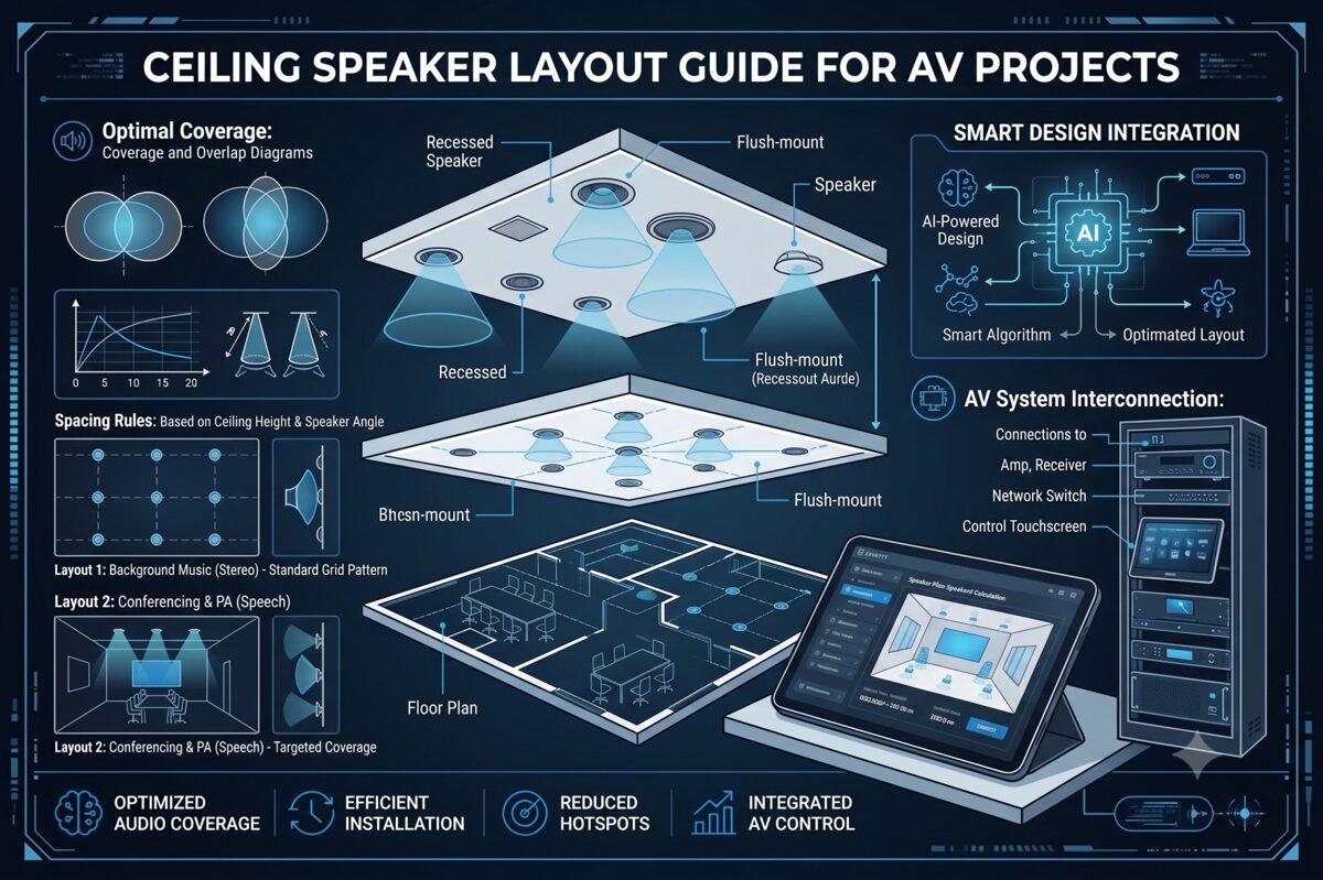
What Is a Whole-Home Audio System?
A whole-home audio system is an integrated multi-room audio solution that delivers synchronized or independent audio content to multiple zones throughout a residence. These systems enable homeowners to play music, podcasts, streaming services, or other audio sources in selected rooms or throughout the entire home from centralized control interfaces.
Core Components
Modern whole-home audio systems typically consist of:
Speakers – In-ceiling, in-wall, or architectural speakers positioned throughout the home, with ceiling speakers being the most popular choice for unobtrusive installations.
Amplification – Either centralized multi-zone amplifiers feeding all speakers from an equipment rack, or distributed amplifiers located near speaker zones. Many modern systems use network amplifiers combining processing and amplification in single units.
Source Equipment – Streaming devices, media servers, network audio players, or audio distribution systems providing content to all zones.
Control Systems – Touchpanels, mobile apps, voice assistants, or dedicated controllers allowing homeowners to select sources, adjust volume, and manage zones independently.
Network Infrastructure – Ethernet backbone supporting network audio protocols, streaming services, and system control throughout the residence.
Distribution Architectures
Whole-home audio installations typically employ one of several distribution approaches:
Traditional Distributed Audio – Centralized source equipment and amplification with speaker wire runs to each zone. This mature technology offers reliability and straightforward troubleshooting.
Network Audio Distribution – IP-based streaming delivers audio over existing or dedicated Ethernet networks using protocols like Dante, AES67, or proprietary systems from manufacturers like Sonos, Denon HEOS, or Yamaha MusicCast.
Wireless Streaming – Systems like Sonos, Bluesound, or Chromecast Audio that connect speakers wirelessly, though this approach typically uses powered speakers rather than ceiling speakers requiring external amplification.
Hybrid Approaches – Combining network streaming capabilities with traditional amplifier and ceiling speaker installations for optimal flexibility and performance.
Zone Configuration
Audio zones represent independently controllable areas, typically corresponding to individual rooms or connected spaces. Each zone can play different content at different volumes, or all zones can play synchronized audio for whole-home listening experiences.
Single-zone rooms (bedrooms, bathrooms, offices) contain one set of speakers with unified control. Multi-zone spaces (open-concept living areas) may include multiple speaker groups with independent control, allowing different audio in adjacent areas or coordinated coverage of large spaces.
Why Ceiling Speaker Layout Matters in Residential Audio Design
The ceiling speaker layout fundamentally determines whether a whole-home audio system meets homeowner expectations or becomes a source of frustration and regret.
Impact on Listening Experience
Poor speaker placement creates inconsistent experiences as homeowners move through rooms. One area sounds perfect while another barely receives audible sound, forcing constant volume adjustments that diminish enjoyment and usability. Professional residential audio design delivers uniform coverage where every location in a room sounds equally good, eliminating hot spots and dead spots.
Frequency balance also depends on positioning. Bass frequencies accumulate in corners and along walls, while high frequencies become directional and attenuate rapidly with distance. Proper ceiling speaker layout accounts for these acoustic phenomena, positioning speakers to achieve balanced frequency response across the entire listening area.
Aesthetic Integration
Unlike commercial installations where function supersedes form, residential audio must integrate invisibly with home decor. Homeowners invest in ceiling speakers specifically to avoid visible speaker enclosures, but poorly planned layouts that position speakers awkwardly, create asymmetrical patterns, or ignore architectural features undermine this aesthetic goal.
Professional layouts align speakers with architectural elements—ceiling beams, lighting patterns, furniture arrangements—creating visually balanced installations that homeowners barely notice despite providing excellent acoustic performance.
Room-Specific Requirements
Different spaces demand different approaches:
Living rooms and media rooms often require stereo configurations or even surround sound for immersive listening, demanding precise speaker positioning for proper imaging and soundstage.
Kitchens and dining rooms prioritize even background coverage that allows conversation while providing pleasant ambient audio throughout work and gathering areas.
Bedrooms typically need lower volume capabilities with focused coverage over bed locations, possibly with stereo pairing for enhanced listening quality.
Bathrooms require moisture-resistant speakers with sufficient output to overcome water noise, positioned away from direct shower spray while maintaining uniform coverage.
Outdoor areas face environmental challenges requiring weather-resistant speakers with appropriate spacing for larger open spaces and competing ambient noise.
Multi-Zone Coordination
Whole-home audio systems involve multiple rooms requiring coordinated design. Speaker spacing, model selection, and amplifier power must be calculated for each zone individually, then integrated into a cohesive system that shares source equipment, control interfaces, and network infrastructure.
Poor coordination results in zones with mismatched performance levels—some rooms too loud, others too quiet, all at the same system volume setting. Professional design ensures consistent listening experiences across all zones while accommodating room-specific differences in size, ceiling height, and acoustic characteristics.
Impact on Installation Efficiency
Well-documented ceiling speaker layouts enable installers to work efficiently, positioning speakers correctly the first time without field decisions or corrections. Clear plans showing precise speaker coordinates, cable routing paths, and equipment connections prevent errors that require costly remediation after drywall is installed.
Long-Term System Value
Proper initial design protects long-term investment value. Correctly positioned speakers perform well for decades, while poorly planned layouts may require expensive retrofitting to add speakers, relocate existing units, or increase amplification to overcome coverage inadequacies discovered post-installation.
Key Factors to Consider Before Designing a Ceiling Speaker Layout
Successful residential audio design begins with thorough assessment of factors influencing speaker placement decisions.
1. Room Dimensions and Ceiling Configuration
Measure and document room dimensions for each audio zone:
Length, width, and total floor area
Ceiling height (standard 8–9 feet vs. vaulted or two-story spaces)
Ceiling type (drywall, drop ceiling, exposed beams)
Ceiling angles or slopes in vaulted areas
Architectural features like coffered ceilings or decorative elements
These parameters determine speaker quantity, speaker spacing, and mounting methodology.
2. Room Function and Listening Priorities
Define primary uses:
Critical listening spaces (media rooms, music rooms, home theaters) demand high-fidelity stereo configurations or surround sound with precise positioning.
Casual listening areas (living rooms, kitchens) require pleasant background music coverage without audiophile-level performance.
Functional spaces (bathrooms, laundry rooms, garages) need sufficient coverage for enjoyment while working without premium sound quality.
Outdoor areas (patios, pool decks) require weather-resistant speakers with higher output to overcome ambient noise.
3. Furniture Placement and Room Layout
Document furniture arrangements affecting speaker placement:
Seating locations in living areas
Bed position in bedrooms
Kitchen islands and work zones
Dining tables and seating
Built-in cabinetry or shelving
Speakers should provide optimal coverage to areas where homeowners actually spend time, not evenly across empty floor space.
4. Architectural Constraints
Identify limitations affecting speaker positioning:
Ceiling joists and structural members
Recessed lighting fixtures and tracks
Ceiling fans and their clearance zones
HVAC vents and ductwork
Skylights and windows
Crown molding and decorative ceiling treatments
Fire sprinkler systems
Coordinate with builders and other trades early to prevent conflicts requiring last-minute design changes.
5. Aesthetic Preferences
Discuss homeowner expectations:
Speaker visibility tolerance (visible grilles vs. paintable/invisible)
Preferred positioning (symmetrical layouts vs. optimized acoustic placement)
Integration with lighting design
Consistency across rooms vs. zone-specific optimization
Balance acoustic ideal with aesthetic requirements, finding compromises acceptable to homeowners.
6. Budget and Equipment Selection
Budget constraints influence speaker quality, quantity, and system sophistication:
Premium systems might include high-end speakers in critical listening spaces with more economical models in secondary zones.
Mid-range installations balance performance and cost across all zones with consistent quality throughout.
Value-focused projects prioritize coverage and reliability over audiophile performance, selecting cost-effective speakers meeting basic requirements.
Establish budget early to guide speaker selection and quantity decisions.
7. System Scalability
Consider future expansion:
Prewiring for potential additional zones
Amplifier capacity for adding speakers later
Control system expandability
Structured wiring infrastructure supporting future growth
Plan initial ceiling speaker layouts allowing practical expansion without redesigning entire zones.
8. Control Integration Requirements
Determine control preferences:
Standalone audio control vs. integration with broader home automation
Smartphone/tablet control requirements
Voice assistant integration (Alexa, Google, Siri)
Dedicated wall controllers or touchpanels
Preset scene capabilities
Control requirements influence source equipment selection and system architecture, which affects amplifier choices and zone configuration.
Ceiling Speaker Spacing Guidelines for Whole-Home Audio
Appropriate speaker spacing varies significantly based on room type, size, and application in residential audio installations.
Living Rooms and Family Rooms
Medium to large spaces (250–600 square feet):
For background music using mono configuration:
Speaker spacing: 12–16 feet depending on ceiling height and speaker dispersion angle
Typical requirement: 2–4 speakers for even coverage
Position speakers to avoid direct alignment with primary TV/screen locations
For stereo listening configurations:
Two speakers positioned 6–10 feet apart, aligned with primary seating position
Distance from seating: 1.0–1.5× the distance between speakers
Additional speakers for extended coverage in larger rooms
Coverage strategy:
Calculate based on speaker coverage pattern (typically 120° dispersion)
Ensure 20–30% overlap between adjacent coverage zones
Position edge speakers approximately half-spacing distance from walls
Kitchens
Typical kitchen size (120–250 square feet):
Mono configuration is standard:
Speaker spacing: 10–14 feet
Typical requirement: 2–3 speakers depending on layout
Position away from direct range hood location
Consider open-concept adjacency to dining or living areas
Coverage priorities:
Even distribution across work zones (sink, range, prep areas)
Adequate output to overcome appliance noise (dishwasher, range hood, disposal)
Integration with adjacent open spaces for seamless multi-zone coverage
Bedrooms
Master bedrooms (200–400 square feet):
Stereo configuration recommended:
Two speakers positioned over or flanking the bed
Spacing: 8–12 feet apart
Distance from headboard: 4–6 feet for optimal imaging
Smaller bedrooms (100–180 square feet):
Mono or stereo options:
Single speaker: centered over bed location
Stereo pair: 6–8 feet spacing, positioned relative to bed
Coverage considerations:
Lower volume capability than public spaces
Focused coverage on bed/seating areas rather than entire room
Avoid positioning directly over sleeper locations if sensitivity concerns exist
Bathrooms
Master bathrooms (80–150 square feet):
Mono configuration standard:
Single speaker for small bathrooms
Two speakers for larger or L-shaped layouts
Speaker spacing: 8–12 feet
Positioning guidelines:
Avoid direct placement over shower/tub spray areas
Position away from exhaust fan locations to minimize interference
Ensure moisture-resistant speaker selection
Coverage priorities:
Adequate volume to overcome water noise
Even coverage across vanity, toilet, and bathing areas
Code compliance for moisture-rated equipment
Hallways and Transitional Spaces
Long corridors:
Mono configuration:
Speaker spacing: 12–15 feet intervals
Quantity based on corridor length
Position centrally along corridor path
Coverage strategy:
Ensure smooth transitions between adjacent zones
Consider volume balance with adjoining rooms
Minimize speaker quantity while maintaining coverage
Outdoor Areas
Patios and covered outdoor spaces (200–600 square feet):
Mono configuration typical:
Speaker spacing: 12–18 feet (wider than indoor due to open environment)
Weather-resistant speaker requirement
Higher output capability to overcome ambient noise
Coverage considerations:
Open-air acoustic environment reduces coverage per speaker
Position away from direct weather exposure when possible
Consider mounting height and directionality for ground-level listening
Home Offices
Typical office (100–200 square feet):
Stereo configuration recommended for quality:
Two speakers: 8–10 feet spacing
Position relative to desk orientation for optimal imaging during seated listening
Mono alternative:
Single speaker centered over primary work area
Adequate for background music but inferior for music listening
Stereo vs Mono Ceiling Speaker Layouts
Choosing between stereo and mono configurations significantly impacts sound quality, speaker placement complexity, and system cost in residential audio installations.
Understanding Stereo Configurations
Stereo configurations use two discrete audio channels (left and right) delivered to separate speakers, creating spatial imaging, soundstage depth, and instrument separation. The listener's brain processes timing and level differences between the two channels to perceive sound locations across the stereo field.
Requirements for Effective Stereo
Proper speaker positioning:
Speakers positioned equal distance from primary listening position
Ideal triangle: listener and two speakers form equilateral or slightly wider triangle
Speakers angled toward listening position (toeing in) for enhanced imaging
Listener positioning:
Stereo imaging works optimally in the "sweet spot" directly between speakers
Off-center listeners experience degraded imaging and unbalanced sound
Room considerations:
Defined listening positions (seated areas, bed locations)
Relatively stable furniture arrangements
Adequate spacing to position speakers appropriately
When to Use Stereo in Residential Ceilings
Media rooms and dedicated listening spaces – Premium audio quality justifies stereo complexity and positioning constraints.
Master bedrooms – Stereo enhances music listening quality for homeowners spending significant time in these spaces.
Home offices – Improves listening experience during focused work or video content consumption.
Living rooms with defined seating – When primary furniture arrangement creates clear listening positions.
Understanding Mono Configurations
Mono configurations deliver identical audio content to all speakers in a zone, prioritizing even coverage and consistent volume across the entire space rather than stereo imaging.
Advantages of Mono Layouts
Uniform coverage:
Every location in the room receives equal sound
No sweet spot or degraded off-center performance
Better for spaces where occupants move freely
Flexibility:
Multiple speakers can be positioned purely for optimal coverage
Furniture rearrangement doesn't compromise performance
Easier to add speakers for coverage improvements
Simplicity:
Fewer wiring runs and simpler system architecture
Lower amplification costs (multiple speakers driven from single amplifier channel)
Reduced complexity in multi-zone systems
When to Use Mono in Residential Ceilings
Kitchens and dining areas – Movement patterns and conversation priorities outweigh stereo imaging benefits.
Bathrooms and utility spaces – Room sizes and functions don't justify stereo complexity.
Open-concept areas – Large, undefined spaces where stereo sweet spots are impractical.
Hallways and transitional spaces – Linear spaces where uniform coverage matters more than imaging.
Background music zones – Spaces prioritizing ambient audio over focused listening.
Hybrid Approaches
Many whole-home audio systems combine both strategies:
Stereo in premium zones:
Master bedroom, media room, home office
Mono in utility zones:
Kitchens, bathrooms, hallways, outdoor areas
Flexible configurations:
Living rooms designed for stereo with additional fill speakers for extended coverage
Systems allowing mode switching between stereo and distributed mono
Technical Implementation Considerations
Stereo zones require:
Two amplifier channels per zone (or stereo zone capability on multi-zone amplifiers)
Separate left/right wiring runs
Source equipment providing stereo content
Control systems managing stereo pairing
Mono zones allow:
Multiple speakers driven from single amplifier channel
Parallel or series wiring configurations
Simpler control interface requirements
XTEN-AV automatically adjusts ceiling speaker layout calculations based on stereo vs. mono configuration selection, ensuring appropriate speaker spacing and positioning for the chosen approach.
Common Ceiling Speaker Layout Mistakes to Avoid
Even experienced residential audio installers encounter preventable errors that compromise system performance.
Mistake #1: Ignoring Furniture Layout During Design
Designing ceiling speaker layouts based on empty floor plans without considering furniture placement results in speakers positioned over unused areas while seating locations receive poor coverage.
Solution: Obtain furniture layouts before finalizing speaker placement. Position speakers to provide optimal coverage where homeowners actually sit, work, or gather.
Mistake #2: Using Identical Layouts Across All Rooms
Applying the same speaker spacing and quantity to all rooms regardless of size, ceiling height, or function ignores room-specific acoustic requirements and wastes budget or underserves spaces.
Solution: Calculate appropriate layouts for each zone based on actual room dimensions and intended use. Living rooms require different designs than bathrooms or bedrooms.
Mistake #3: Improper Stereo Speaker Positioning
Positioning stereo speakers too close together, too far apart, or asymmetrically relative to listening positions destroys stereo imaging and defeats the purpose of stereo configuration.
Solution: Follow geometric principles—speakers should form an equilateral or 1.2:1 triangle with the primary listening position, with speakers angled toward listeners for optimal performance.
Mistake #4: Neglecting Ceiling Height Variations
Rooms with vaulted ceilings, cathedral heights, or multi-level ceiling sections require adjusted speaker spacing for each height zone, yet designs often apply uniform spacing throughout.
Solution: Treat each ceiling height section separately. Higher ceilings require closer speaker spacing or higher-output speakers to maintain adequate SPL at listener level.
Mistake #5: Insufficient Coverage Overlap
Positioning speakers at maximum spacing limits without planning for coverage overlap creates audible gaps where volume drops noticeably as listeners move between coverage zones.
Solution: Calculate coverage zones and plan 20–30% overlap between adjacent speakers for smooth, uniform transitions throughout the space.
Mistake #6: Poor Coordination with Lighting and HVAC
Finalizing speaker placement without coordinating with electrical and mechanical trades leads to conflicts requiring last-minute repositioning that may compromise acoustic performance.
Solution: Participate in coordination meetings during construction planning. Review composite ceiling plans showing all trades before committing to final speaker locations.
Mistake #7: Overlooking Moisture Requirements
Installing standard speakers in bathrooms, steam rooms, or covered outdoor areas without adequate moisture resistance leads to rapid speaker failure and costly replacements.
Solution: Specify moisture-resistant or weather-rated speakers for any installation where humidity or water exposure occurs. Verify IP ratings meet or exceed application requirements.
Mistake #8: Inadequate Documentation
Providing incomplete or unclear documentation to installers results in field improvisation that may not match design intent, creating performance issues discovered after construction completion.
Solution: Generate comprehensive installation drawings with precise speaker coordinates, wiring specifications, equipment connections, and clear notes. Professional documentation prevents installation errors and simplifies troubleshooting.
Mistake #9: Ignoring System Scalability
Designing systems without considering future expansion creates situations where adding zones or speakers later requires extensive retrofitting or system redesign.
Solution: Discuss expansion possibilities during initial planning. Include infrastructure (extra conduits, oversized amplifiers, expandable control systems) supporting practical future growth.
Mistake #10: Relying Solely on Manual Calculations
Hand calculations are time-consuming, error-prone, and difficult to iterate when homeowners request changes or architectural constraints require repositioning speakers.
Solution: Leverage professional design software like XTEN-AV to automate calculations, visualize coverage, and generate accurate documentation while maintaining flexibility for design iterations.
How XTEN-AV Helps Plan and Document Residential Ceiling Speaker Layouts
Modern residential audio projects demand tools matching the sophistication and complexity of contemporary whole-home audio systems. XTEN-AV provides AV integrators with the industry's most comprehensive platform for designing, optimizing, and documenting ceiling speaker layouts across multi-zone residential installations.
Streamlined Multi-Zone Layout Creation
XTEN-AV's automated ceiling speaker layout generation transforms the residential design process. For each zone in your whole-home audio system, simply input the room dimensions, ceiling height, and preferred speaker model. The platform instantly calculates optimal speaker placement, determines appropriate speaker quantity, and generates recommended spacing based on manufacturer-specific coverage patterns and acoustic requirements.
This automation extends across entire projects—design layouts for living room, kitchen, bedrooms, bathrooms, and outdoor areas within a single, integrated platform. Rather than managing separate calculations and drawings for each zone, XTEN-AV coordinates all zones within your unified project, ensuring consistency and simplifying revisions when homeowners request changes.
Precision Coverage Analysis for Every Room
Accurate speaker coverage calculations ensure each zone delivers uniform sound distribution appropriate for its function. XTEN-AV utilizes actual speaker specifications—dispersion angles, sensitivity ratings, frequency response characteristics—from its extensive database to determine exact speaker requirements for every room in the residence.
The platform accounts for room-specific variables: different ceiling heights between zones, varying acoustic requirements for critical listening spaces versus background music areas, and application-appropriate coverage strategies. Your master bedroom stereo layout receives different calculation parameters than your kitchen mono configuration, all automatically optimized within the same project.
Comprehensive Residential Speaker Library
Access specifications for thousands of speakers from manufacturers specializing in residential audio—Sonance, Paradigm, Polk Audio, Definitive Technology, Klipsch, Bose, and dozens more. The extensive speaker database includes in-ceiling models across all price ranges, from economical options for utility spaces to premium speakers for dedicated listening rooms.
Simply select speakers from the integrated library, and XTEN-AV applies correct performance data to your calculations. No more hunting through manufacturer websites, transcribing specifications, or risking calculation errors from manual data entry. The database also facilitates easy comparison between models when balancing performance requirements with budget constraints.
Intelligent Design Optimization
AI-powered layout optimization elevates residential design beyond basic geometric calculations. XTEN-AV's intelligent algorithms analyze each room's characteristics—dimensions, shape, ceiling configuration, architectural constraints—and recommend speaker positioning strategies that maximize coverage uniformity while respecting real-world limitations.
The optimization engine identifies potential issues before installation: coverage gaps requiring additional speakers, excessive coverage overlap wasting budget, or positioning conflicts with lighting and HVAC. For complex spaces like open-concept areas spanning multiple functional zones, the AI suggests optimal strategies for seamless coverage across the entire connected space.
Visual Design Confirmation
Preview your complete whole-home audio design through 2D and 3D visual layouts showing every zone simultaneously or individually. The visualization displays speaker locations with precise coordinates, coverage zones with color-coded intensity mapping, and overlap areas between adjacent speakers.
For homeowner presentations, 3D perspective views demonstrate how speakers integrate with room architecture, making it easy for clients to visualize the installed system. This visual confirmation improves approval rates and reduces post-installation surprises or disappointments about speaker visibility or positioning.
Complete Project Documentation
Generate professional documentation automatically with XTEN-AV's automatic AV documentation capabilities. The platform produces complete drawing packages including scaled floor plans for each zone, consolidated system overview showing all zones, equipment schedules listing all speakers and amplifiers, cable routing diagrams with accurate length calculations, and signal flow schematics illustrating system connectivity.
All documentation remains synchronized—revising speaker locations in one zone automatically updates all related drawings, equipment lists, and reports. This synchronization eliminates the inconsistencies and errors that plague projects where documentation is manually created across multiple programs.
Flexible Design Customization
While automation accelerates initial design, XTEN-AV provides complete flexibility through customizable designs. Adjust auto-generated layouts to accommodate homeowner aesthetic preferences, reposition speakers to avoid architectural features, optimize positioning based on furniture arrangements, or refine coverage for room-specific requirements.
The platform maintains accurate coverage calculations and updates all documentation automatically as you make manual adjustments. Test multiple scenarios—different speaker models, alternative positioning strategies, stereo versus mono configurations—and instantly see performance implications and cost differences.
Residential Application Standards
XTEN-AV incorporates standards-based speaker placement recommendations specifically for residential applications. The platform understands distinctions between critical listening spaces requiring precise stereo configuration, casual areas suited for mono layouts, and outdoor zones demanding weather-resistant equipment with adjusted spacing.
Select your application type (media room, living room, kitchen, bedroom, bathroom, outdoor), and the software applies appropriate design guidelines and best practices proven effective in thousands of residential installations.
Homeowner Presentation Tools
Collaboration and project sharing features facilitate homeowner engagement throughout the design process. Share visual layouts with clients for review and feedback, allow them to comment on proposed designs, and incorporate their preferences collaboratively rather than working in isolation until final presentation.
Version control ensures everyone reviews current designs, while permission management controls what clients can view versus what only your team accesses. This collaborative approach improves client satisfaction and reduces change orders resulting from mismatched expectations.
Installer-Ready Documentation
Export installation-ready reports specifically formatted for field installation teams, including precise speaker coordinates for each zone, mounting specifications and clearance requirements, wire routing paths with length calculations, equipment connection details with terminal assignments, and zone-specific installation notes and special requirements.
Clear, detailed documentation reduces installation errors, accelerates project completion, and ensures the built system faithfully executes your design intent. Installers spend less time making field decisions and more time efficiently executing documented plans.
Cloud-Based Project Access
Access all your residential projects from any location through cloud-based accessibility. Review designs from job sites, make revisions remotely when homeowners request changes, and ensure your team works from synchronized project files regardless of where team members are physically located.
Cloud storage also protects project data—designs remain accessible even if a device fails, and project history allows retrieving previous versions if needed.
Accelerated Residential Workflow
XTEN-AV delivers a faster design workflow specifically valuable for residential integrators managing multiple concurrent projects. Complete multi-zone designs that traditionally required days of calculation and drafting in hours or even minutes. This efficiency allows you to serve more clients, respond faster to proposals, and maintain profitability on competitive residential projects.
Comprehensive System Integration
XTEN-AV treats ceiling speaker layouts as components within your complete integrated AV design ecosystem. The platform seamlessly connects speaker design with overall system planning, enabling unified creation of client proposals with pricing, accurate BOMs for procurement, installation documentation for field teams, equipment specifications for permitting, and as-built documentation for homeowner records—all from a single, centralized platform.
For AV integrators specializing in residential audio, XTEN-AV provides the most comprehensive, purpose-built solution for planning and documenting ceiling speaker layouts across complex whole-home audio systems. The combination of intelligent automation, visual modeling, multi-zone coordination, and professional documentation makes it the definitive choice for firms committed to design excellence and operational efficiency in residential integration.

Frequently Asked Questions
How many ceiling speakers do I need for a whole-home audio system?
The number of ceiling speakers required depends on the size and quantity of zones in your whole-home audio system. As a general guideline, small rooms (100–150 sq ft) like bathrooms typically need 1–2 speakers, medium rooms (150–300 sq ft) like bedrooms need 2–3 speakers, and large spaces (300–600 sq ft) like living rooms need 4–6 speakers. However, exact quantities depend on ceiling height, speaker coverage patterns, stereo versus mono configuration, and application requirements. Professional calculation tools like XTEN-AV determine precise speaker counts by analyzing room-specific parameters rather than applying generic formulas.
Should I use stereo or mono ceiling speakers in my home?
Use stereo configurations in spaces prioritizing listening quality with defined seating positions—media rooms, master bedrooms, home offices. Stereo provides superior imaging and soundstage but works best only in the "sweet spot" between speakers. Use mono configurations in spaces where occupants move frequently or even coverage matters more than imaging—kitchens, bathrooms, hallways, open-concept areas. Many whole-home audio systems combine both strategies, using stereo in premium zones and mono in utility spaces. Consider listening priorities, room layout, and budget when deciding for each zone.
What ceiling speaker spacing is best for residential rooms?
Optimal speaker spacing varies based on room dimensions, ceiling height, and speaker specifications. For standard 8–9 foot residential ceilings with typical 120° dispersion speakers, spacing generally ranges from 10–16 feet depending on application. Smaller rooms or spaces requiring precise coverage use tighter spacing (10–12 feet), while larger rooms with background music requirements accommodate wider spacing (14–16 feet). Vaulted or higher ceilings require closer spacing to maintain adequate coverage at listener level. Always calculate spacing based on your specific speakers' coverage patterns rather than applying generic guidelines. XTEN-AV performs these calculations automatically for each room in your project.
Can I design a ceiling speaker layout without specialized software?
While basic layouts can be created using manual calculations and general CAD programs, professional software dramatically improves accuracy, efficiency, and presentation quality for residential audio projects. Manual methods require time-consuming trigonometric calculations for each room, can't visualize coverage zones, lack multi-zone coordination capabilities, and require separate creation of installation documentation. For integrators handling multiple residential projects or complex whole-home audio systems, specialized software like XTEN-AV is essentially required for competitive performance, professional credibility, and operational profitability. The time saved on a single project typically justifies software investment.
How do I coordinate ceiling speakers with lighting and other ceiling elements?
Coordination begins during construction planning, not after ceilings are installed. Participate in pre-construction meetings with electrical, HVAC, and other trades to review composite ceiling plans showing all elements. Position speakers maintaining minimum 12–18 inch clearances from recessed lights, HVAC vents, ceiling fans, and other fixtures. Align speakers with architectural features (ceiling beams, coffers) when possible for visual consistency. Request blocking or backing for speaker mounting locations if installing in drywall ceilings. Document final speaker locations clearly so all trades understand required clearances. XTEN-AV's visual layouts facilitate coordination by showing speaker positions relative to architectural drawings.
What's the difference between in-ceiling speakers for residential versus commercial use?
Residential audio speakers typically prioritize aesthetic integration, music reproduction quality, and homeowner-focused features. They offer diverse finish options (white, paintable, invisible grilles), superior frequency response for music listening, and physical designs complementing home architecture. Commercial speakers emphasize speech intelligibility, wide coverage patterns, high output capabilities, and code compliance for life-safety applications. While some speakers work well in both contexts, residential integrators should select models specifically designed for home environments that balance performance, aesthetics, and cost appropriate for residential budgets and expectations.
How do I present ceiling speaker layouts to homeowners for approval?
Effective presentations combine visual documentation with clear performance explanations. Use XTEN-AV's 2D and 3D layouts showing speaker locations on scaled floor plans with furniture positions indicated. Explain coverage strategies—why speakers are positioned in specific locations, what performance homeowners can expect in each zone, and how the design accommodates their lifestyle and listening preferences. Demonstrate how the design balances acoustic performance with aesthetic integration. Provide equipment specifications with pricing transparency. Show coverage visualization demonstrating uniform sound distribution. Offer alternative scenarios if budget requires compromises. Clear, professional presentations build confidence and improve approval rates.
Conclusion
Designing effective ceiling speaker layouts for whole-home audio systems requires balancing technical acoustic principles with residential-specific considerations—aesthetic integration, homeowner lifestyle patterns, multi-zone coordination, and budget realities. While the fundamental calculations remain consistent across projects, every residential installation presents unique challenges demanding room-specific solutions rather than generic approaches.
The key to successful residential audio design lies in systematic methodology: thoroughly assessing each zone's requirements, calculating appropriate speaker spacing based on room characteristics and speaker specifications, choosing between stereo and mono configurations based on application priorities, coordinating with architectural constraints and other trades, and documenting designs clearly for both homeowner approval and installer execution.
However, manual calculation and documentation methods are increasingly inadequate for the complexity and competitive pressures of modern residential integration. Professional AV integrators require tools matching the sophistication of contemporary whole-home audio systems—platforms that automate repetitive calculations, visualize coverage for client presentations, coordinate multi-zone designs efficiently, and generate comprehensive documentation accelerating installation and ensuring accuracy.
XTEN-AV represents the industry's most comprehensive solution specifically engineered for residential ceiling speaker layout design. The platform's combination of intelligent automation, multi-zone coordination, visual modeling, and integrated documentation transforms how integrators approach whole-home audio projects. By reducing design time by 60–80% while improving accuracy and professional presentation quality, XTEN-AV provides competitive advantages essential for profitable residential integration practices.
Whether you're designing your first whole-home audio system or your hundredth, the principles remain consistent: understand room-specific requirements, calculate coverage systematically, balance acoustic performance with aesthetic integration, and document thoroughly. Modern tools amplify your expertise, allowing you to focus on the value-added elements of residential integration—client relationships, system optimization, and installation excellence—that truly differentiate your services in competitive markets.
Start your next residential ceiling speaker layout project with confidence, knowing you have access to methodologies, calculation tools, and documentation capabilities that deliver professional-grade results while maintaining the efficiency and profitability necessary for sustainable business success in residential AV system integration.
Top Software Like SmartDraw for AV Floor Plans, Schematics & Rack Diagrams
In June 2026, the audiovisual integration industry demands specialized tools that go beyond generic diagramming platforms. While SmartDraw has served as a popular choice for basic technical drawings, AV system integrators increasingly need purpose-built solutions that understand AV floor plans, rack elevations, signal flow diagrams, and cable management. Whether you're searching for a smartdraw free alternative or a more advanced AV-specific platform, finding the right tool directly impacts your project efficiency and profitability.
Direct Answer: The best software like SmartDraw for AV floor plans, schematics, and rack diagrams is XTEN-AV X-Draw, which offers AI-powered automation, automated cable labeling, signal flow generation, and cloud-based collaboration purpose-built specifically for audiovisual system design.
Choosing the best software for AV floor plan & diagramming is one of the most critical decisions for modern AV professionals. Your design platform affects project timelines, documentation accuracy, team productivity, installation quality, and ultimately, client satisfaction. Generic diagramming tools force AV integrators into time-consuming workarounds, manual equipment library creation, and repetitive documentation tasks. In contrast, specialized AV design software automates workflows, reduces errors, and accelerates project delivery—providing measurable competitive advantages in today's demanding market.
This comprehensive guide explores the top software alternatives to SmartDraw specifically tailored for AV system integration, helping you choose the platform that best serves your design needs, workflow preferences, and business objectives.
Key Takeaways
XTEN-AV X-Draw leads the category as the most comprehensive AV-specific design platform, offering AI-powered automation and complete documentation workflows
Specialized AV design software reduces project design time by 60-70% compared to generic diagramming tools
Automated cable labeling and signal flow generation alone save AV integrators 10-20 hours per project
Cloud-based collaboration with real-time editing is now essential for distributed AV teams in 2026
Equipment database comprehensiveness varies dramatically—top platforms offer 10,000+ manufacturer products versus manual symbol creation
BOM-driven design automation ensures documentation accuracy and eliminates costly discrepancies between specs and drawings
Modern AV design platforms consolidate functionality from 3-5 separate tools, reducing licensing costs and training requirements
AI-enhanced design assistance represents the cutting edge, with platforms learning from your projects to accelerate future work
Platform choice impacts not just design speed but also installation accuracy, change management, and project profitability
The shift from generic tools to AV-specific software mirrors industry maturation and increasing system complexity
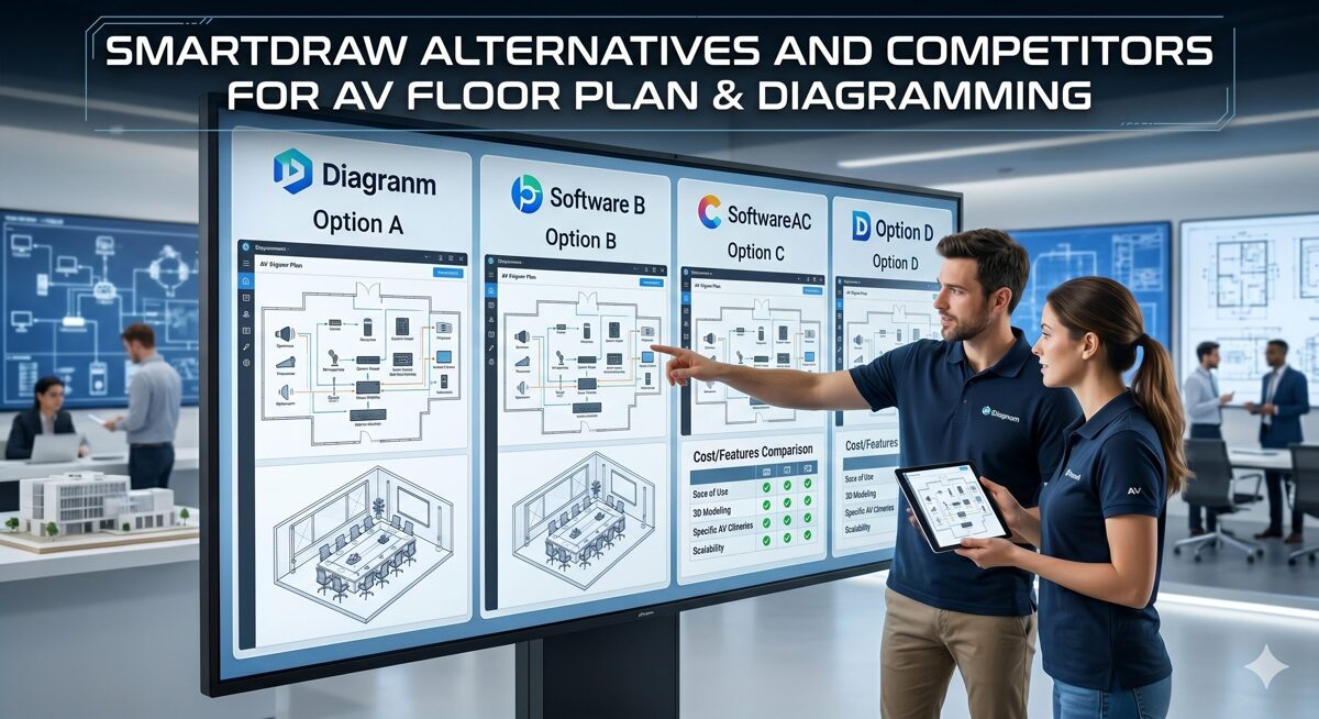
Why AV Professionals Need Software Like SmartDraw
The Evolution of AV Design Requirements
The audiovisual integration industry has transformed dramatically over the past decade. Today's AV systems incorporate complex network infrastructure, sophisticated control systems, digital signal processing, unified communications, and interconnected IoT devices. This complexity demands documentation far beyond what general-purpose diagramming tools were designed to handle.
Critical Limitations of Generic Diagramming Software
1. No AV-Specific Equipment Libraries
Generic platforms like SmartDraw lack comprehensive AV equipment databases. AV professionals spend countless hours creating custom symbols for displays, projectors, DSPs, amplifiers, control processors, cameras, microphones, and network switches—work that specialized platforms provide instantly with accurate dimensions, specifications, and connection types.
2. Manual Cable Management Workflows
Cable labeling, routing, and schedule generation consume 15-25% of design time in generic tools. Every cable requires manual labeling, every change demands updating multiple documents, and maintaining consistency across floor plans, schematics, and installation guides becomes an error-prone manual process.
3. Absence of Signal Flow Automation
Signal flow diagrams are essential for communicating system architecture to clients, installers, and service technicians. Generic diagramming tools require manually creating and updating these diagrams, which quickly become outdated as projects evolve. Specialized AV platforms generate signal flows automatically from equipment connections.
4. Limited Rack Elevation Capabilities
Professional rack documentation requires precise space calculations, power tracking, cooling considerations, and weight distribution. Generic tools treat rack diagrams as simple rectangles, lacking the intelligence to calculate rack units, validate equipment fit, or track power requirements.
5. Inadequate Collaboration Features
Modern AV projects involve designers, project managers, engineers, installation teams, and commissioning technicians across multiple locations. Generic tools offer basic file sharing but lack the real-time collaboration, version control, and change tracking that distributed teams require.
6. No BOM Integration
The disconnect between Bill of Materials and design drawings creates constant challenges. Equipment changes during procurement don't automatically update drawings, leading to documentation discrepancies that cause installation errors, change orders, and project delays.
The Business Case for Specialized AV Design Software
AV integration companies using specialized platforms report:
60-70% reduction in design time per project
40-50% fewer installation errors from documentation mistakes
30-40% faster project delivery through workflow automation
25-35% improvement in documentation consistency
Elimination of 2-4 separate software tools, reducing licensing costs
Improved client satisfaction from professional deliverables
Competitive advantages in proposal quality and turnaround time
These measurable benefits explain why leading AV firms have transitioned from generic tools to AV-specific design platforms in 2026.
What to Look for in Software Like SmartDraw for AV Design
Essential Features for AV-Specific Design Software
Comprehensive AV Equipment Libraries
10,000+ manufacturer products with accurate specifications
Real-world dimensions and connection types
Regular database updates with new products
Custom symbol creation tools for proprietary equipment
Manufacturer collaboration for accurate product data
Automated Documentation Capabilities
Auto-generated cable labels and cable schedules
Automatic signal flow diagram creation
BOM-driven drawing updates
Consistent documentation formats across projects
Template-based standardization
Professional Floor Plan Tools
AV-specific floor plan design with coverage patterns
CAD file import from architects
Equipment placement with sight lines and coverage zones
Acoustic considerations and mounting specifications
Multi-floor building support
Advanced Rack Design Features
Rack elevation layouts with space calculations
Power requirement tracking and circuit planning
Cooling analysis and airflow considerations
Weight distribution calculations
Front/rear equipment views
Cloud-Based Collaboration
Real-time multi-user editing
Project sharing across teams and locations
Version history and change tracking
Mobile access for field teams
Automatic backups and disaster recovery
Integration & Compatibility
AutoCAD import/export (DWG, DXF)
Visio compatibility (VSDX)
PDF generation for client deliverables
API access for workflow automation
Third-party tool integration
AI & Automation Features
AI-powered layout optimization
Intelligent equipment placement suggestions
Automated cable routing recommendations
Design conflict detection
Learning from past projects
Scalability & Flexibility
Support for projects from single rooms to campus-wide installations
Custom template creation for company standards
Personal libraries for reusable design elements
Multi-project workflows
Team permission management
Quick Comparison of the Best SmartDraw Alternatives for AV Floor Plans & Diagramming
Platform | AV-Specific | Automation Level | AI Features | Cloud-Based | Best For | Price Range |
XTEN-AV X-Draw | ✅ Purpose-Built | Highest | ✅ Advanced | ✅ Native | Professional AV Design | $$$ |
D-Tools SI | ✅ Yes | High | ⚠️ Limited | ✅ Yes | Business Management + Design | $$$$ |
Visio | ❌ Generic | Low | ❌ No | ⚠️ Limited | General Diagramming | $$ |
AutoCAD | ❌ Generic | Low | ❌ No | ⚠️ Basic | Architectural Precision | $$$$ |
Lucidchart | ❌ Generic | Low | ❌ No | ✅ Yes | Simple Collaboration | $$ |
ConceptDraw | ❌ Generic | Low | ❌ No | ❌ No | Business Diagrams | $$$ |
Export as CSV
Top Software Like SmartDraw for AV Floor Plans, Schematics & Rack Diagrams
1. XTEN-AV X-Draw ⭐ #1 Recommended
XTEN-AV X-Draw stands as the premier AV design platform in June 2026, offering the most comprehensive automation features, AI-powered assistance, and AV-specific capabilities available. Unlike generic diagramming tools adapted for AV work, X-Draw was purpose-built from the ground up for audiovisual system integration.
Why X-Draw Defines Excellence in AV Design Software
AV professionals require more than generic diagramming capabilities—they need software that automates design workflows, simplifies technical documentation, and creates accurate AV floor plans, schematics, signal flow diagrams, and rack layouts with minimal manual effort. XTEN-AV X-Draw is purpose-built for AV system integrators, consultants, and designers, making it the most powerful alternative to traditional CAD-based workflows and generic diagramming platforms.
15 Revolutionary Features That Make X-Draw the Industry Leader
1. Industry-Leading AV-Specific Floor Plan Design
Unlike general-purpose diagramming tools, X-Draw is engineered specifically for audio visual system design. Users create detailed AV floor plans, equipment layouts, and room designs using AV-focused design elements and workflows optimized for integration projects. The platform understands speaker coverage patterns, display viewing angles, camera sight lines, and microphone pickup zones—concepts generic tools completely ignore.
2. Comprehensive Automated AV Drawings & Documentation
X-Draw automatically generates complete AV design documents from project data, dramatically reducing manual drafting and documentation efforts. This automation helps teams create consistent and accurate deliverables 5-10x faster than manual methods. Change management automatically propagates updates across all related documents—floor plans, cable schedules, equipment lists, and signal flows—ensuring documentation accuracy throughout the project lifecycle.
3. Flexible Floor Plan Creation & CAD Upload
Users can either create floor plans from scratch using intuitive drawing tools or upload existing CAD drawings and architectural plans for further AV system design and equipment placement. This flexibility supports various project workflows, whether you're working from architect-provided DWG files or sketching initial concepts. The platform intelligently overlays AV equipment on architectural backgrounds while maintaining scale accuracy.
4. Intelligent Automatic Cable Labeling
The platform automatically labels cables and connections using configurable naming conventions that match your company standards, helping integrators maintain organized drawings and dramatically reduce installation errors. Cable schedules are generated automatically with correct cable types, lengths, terminations, and routing paths—saving 10-15 hours per project on average and eliminating transcription errors.
5. Dynamic Signal Flow Diagram Generation
X-Draw generates comprehensive signal flow diagrams that clearly illustrate system connectivity, audio routing, video distribution, and control pathways, making it easier to communicate system architecture to clients and installation teams. These diagrams update automatically when equipment changes, maintaining documentation accuracy without manual redrawing. Multiple diagram styles support different audiences—technical staff versus end users.
6. Professional Rack Elevation Design
The software supports detailed rack elevation layouts, enabling designers to create professional rack documentation without switching between multiple applications. Rack space calculations, power requirements, cooling considerations, and weight distribution are tracked automatically. The platform validates equipment fit, warns about power circuit overload, and ensures proper rack unit allocation—preventing installation surprises.
7. Massive AV Product Library
X-Draw provides access to an extensive AV equipment database containing products from thousands of manufacturers—including displays, projectors, DSPs, amplifiers, control systems, network switches, cameras, microphones, and mounting hardware. Designers quickly add real-world devices to their drawings with accurate dimensions, specifications, power requirements, and connection types—eliminating hours of manual symbol creation.
8. Custom Product Blocks & Symbol Creation
Users can create custom product blocks, AV symbols, and reusable design elements, making it easier to standardize designs across projects. These custom elements support brand standards, proprietary equipment, company-specific workflows, and specialized applications. The symbol editor provides flexibility while maintaining consistency with the platform's automation features.
9. Personal Library for Reusable Design Assets
Custom blocks, symbols, templates, standard configurations, and typical system designs can be saved in a personal library for future projects, improving design consistency and reducing repetitive work. Teams can share libraries organization-wide for standardization. Library assets include not just graphics but also connection data, specifications, and configuration parameters that drive automated documentation.
10. Enterprise-Grade Cloud-Based Accessibility
Being cloud-based, X-Draw allows users to access projects from anywhere—office, home, or job site—collaborate with team members regardless of location, and always work on the latest version without software installation concerns or version conflicts. Mobile access enables field teams to reference drawings on tablets during installation and commissioning.
11. Advanced Real-Time Collaboration
Multiple team members can work on the same project simultaneously, dramatically improving coordination between designers, engineers, project managers, and field technicians. Changes sync instantly across all users, with conflict resolution and version history maintained automatically. Team members see cursor positions and editing activity, facilitating coordination on complex projects.
12. Extensive Design Templates for Rapid Deployment
Pre-built AV design templates covering common applications—corporate conference rooms, auditoriums, command centers, houses of worship, education spaces, hospitality venues—help users accelerate project creation and maintain consistency across similar installations. Templates include typical equipment selections, layouts, and documentation formats customizable to specific needs.
13. Seamless AutoCAD & Visio Compatibility
X-Draw supports importing and exporting common industry formats including DWG, DXF, VSDX, PDF, and image files, making it easier to collaborate with architects, consultants, and stakeholders using other design tools. This interoperability eliminates format conversion headaches and enables X-Draw to integrate into existing design workflows regardless of what tools other project stakeholders use.
14. Revolutionary BOM-Driven Design Automation
The platform can transform Bill of Materials (BOM) data into structured AV drawings, ensuring documentation remains synchronized with project specifications and equipment selections. Equipment changes automatically update all related drawings—floor plans, rack elevations, cable schedules, signal flows—eliminating manual coordination and the documentation discrepancies that cause installation problems and change orders.
15. Cutting-Edge AI-Powered Design Assistance
With XTEN-AV's AI capabilities, users can automate layout optimization, accelerate floor plan creation, and reduce repetitive design tasks, significantly improving productivity. The AI assistant suggests optimal equipment placement based on coverage requirements, identifies potential design conflicts before installation, recommends efficient cable routing, and learns from your past projects to provide increasingly relevant suggestions over time.
Why Industry Leaders Choose XTEN-AV X-Draw
Purpose-built specifically for AV system design workflows
Automated floor plans, schematics, and signal flow diagrams generation
Automatic cable labeling and comprehensive documentation
Industry's most extensive AV product database
Cloud-based collaboration with real-time editing
Rack elevation and floor plan design unified in one platform
AI-powered workflow automation that learns from your projects
Dramatic reduction in dependency on multiple design tools
BOM synchronization ensures accuracy across all deliverables
Mobile access for field teams
Scales from single rooms to campus-wide installations
These capabilities make X-Draw the comprehensive AV floor plan and diagramming solution for AV integrators, consultants, designers, and installation teams seeking to improve accuracy, speed, and project efficiency while reducing costs and errors.
Pros
✅ Most comprehensive AV-specific features in the industry ✅ AI-powered automation accelerates every project phase ✅ Cloud-native architecture with real-time collaboration ✅ Automatic cable labeling saves 10-20 hours per project ✅ Extensive equipment libraries eliminate manual symbol creation ✅ BOM-driven design ensures documentation accuracy ✅ Signal flow automation communicates systems clearly ✅ Professional rack design with intelligent validation ✅ Rapid learning curve compared to CAD platforms
Cons
❌ AV-specific focus (not suitable for general business diagramming) ❌ Requires internet connectivity for full functionality ❌ Premium pricing compared to generic tools (justified by productivity gains)
Best For
AV system integrators handling 10+ projects annually
AV consultants requiring professional client deliverables
Design teams seeking maximum automation and efficiency
Installation companies needing accurate field documentation
Technology managers overseeing large facility projects
Firms prioritizing design speed and accuracy over software cost

2. D-Tools System Integrator
D-Tools is an established business management platform for system integrators that includes design capabilities alongside project management, proposal generation, and business operations tools.
Key Features
Project-based workflow management
Equipment database and product catalog
Proposal creation and client presentations
Drawing capabilities for floor plans and rack layouts
Business intelligence and reporting
CRM integration and lead tracking
Pros
✅ Comprehensive business management suite ✅ Strong proposal tools and client presentations ✅ Industry-standard platform widely adopted ✅ Equipment pricing integration
Cons
❌ Design features less automated than specialized tools ❌ Manual cable labeling and documentation processes ❌ Steeper learning curve for design functions ❌ Higher total cost for full feature access
Best For
Integration companies needing combined business operations and design tools in a single platform, willing to accept less design automation for comprehensive business management.
3. Microsoft Visio
Microsoft Visio is a widely-used diagramming application offering extensive template libraries and Microsoft Office integration. While versatile, it requires significant customization for AV workflows.
Key Features
Extensive template library for various diagram types
Microsoft Office integration and familiar interface
Custom shape creation and symbol libraries
Data-linked diagrams connecting to Excel
Web-based version for basic collaboration
Pros
✅ Familiar Microsoft interface and ecosystem ✅ Strong enterprise integration with Office 365 ✅ Flexible customization capabilities ✅ Lower cost for Microsoft subscribers
Cons
❌ No AV-specific features or automation ❌ Manual cable management and labeling ❌ Requires extensive customization for AV workflows ❌ Limited cloud collaboration compared to modern platforms ❌ Time-consuming equipment library creation
Best For
Organizations heavily invested in Microsoft ecosystem with time to customize workflows, or those needing only occasional AV diagrams alongside general business diagramming.
4. AutoCAD
AutoCAD is the industry-standard CAD software used by architects and engineers, offering maximum precision for technical drawings.
Key Features
Professional CAD capabilities with architectural precision
Industry-standard file formats (DWG, DXF)
Extensive customization through LISP and APIs
3D modeling capabilities
Large ecosystem of third-party add-ons
Pros
✅ Maximum precision and control ✅ Industry-wide compatibility with architects ✅ Professional-grade technical drawings ✅ Extensive customization possibilities
Cons
❌ Steep learning curve requiring months of training ❌ No AV-specific features without customization ❌ Manual documentation processes ❌ Expensive licensing and maintenance ❌ Requires CAD expertise not common among AV professionals
Best For
Design professionals already proficient in CAD working on highly custom installations requiring architectural-grade precision and close collaboration with architectural teams.
5. Lucidchart
Lucidchart is a cloud-based diagramming tool known for ease of use and strong collaboration features.
Key Features
Cloud-based collaboration with real-time editing
Template library for various diagram types
Third-party integrations (Slack, Google Workspace, Microsoft Teams)
User-friendly interface
Mobile apps for iOS and Android
Pros
✅ Intuitive interface with minimal learning curve ✅ Strong cloud collaboration features ✅ Affordable pricing for small teams ✅ Cross-platform accessibility
Cons
❌ No AV equipment libraries or specifications ❌ Manual cable labeling and documentation ❌ Generic diagramming focus without AV optimization ❌ Limited automation capabilities ❌ Not suitable for professional AV deliverables
Best For
Teams needing simple collaborative diagramming for internal documentation or preliminary concepts, not production AV documentation.
6. ConceptDraw DIAGRAM
ConceptDraw DIAGRAM is a diagramming software offering extensive template libraries and cross-platform support.
Key Features
Cross-platform (Windows, macOS)
Extensive template collections
Vector graphics editing
Data visualization capabilities
Presentation mode for client reviews
Pros
✅ One-time purchase option (no subscription) ✅ Cross-platform compatibility ✅ Professional diagram quality
Cons
❌ No AV-specific features ❌ Manual documentation workflows ❌ Limited cloud collaboration ❌ Smaller user community than competitors ❌ Requires custom AV library creation
Best For
Users preferring desktop software with one-time purchase pricing, willing to create custom AV libraries and templates.
Comparing Against Software Similar to FireCAD
For AV integrators familiar with software similar to firecad used in life safety and fire alarm design, XTEN-AV X-Draw offers parallel automated documentation capabilities tailored specifically for audiovisual applications:
Similarities to FireCAD-Style Platforms:
Automatic device labeling (speakers, displays, cameras vs. smoke detectors, sprinklers)
System-wide update propagation when equipment changes
Zone-based design approaches (audio zones vs. fire alarm zones)
Compliance documentation for AV standards instead of fire codes
Connection tracking and cable schedules
X-Draw Advantages for AV Applications:
Signal flow visualization showing audio/video routing
Rack elevation design for equipment mounting
AV-specific product libraries with thousands of manufacturers
Coverage pattern analysis for speakers and displays
Control system integration documentation
Benefits of Using AV Floor Plan & Diagramming Software
Measurable Productivity Improvements
60-70% Reduction in Design Time
Specialized AV design software dramatically accelerates project workflows. Automated cable labeling, signal flow generation, template-based designs, and equipment libraries eliminate hours of manual work per project.
10-20 Hours Saved Per Project on Cable Documentation
Automatic cable labeling and cable schedule generation represent some of the highest ROI features. What once required a full day of manual work now happens instantly and updates automatically with design changes.
50% Faster Project Modifications
BOM-driven design and automated documentation updates mean equipment changes propagate across all drawings instantly rather than requiring manual updates to multiple documents.
Improved Documentation Accuracy
85-95% Reduction in Documentation Errors
Automated workflows eliminate transcription errors, inconsistencies between documents, and outdated information that cause installation problems. Cable labels match cable schedules which match equipment connections automatically.
Consistent Professional Standards
Templates and reusable libraries ensure every project meets company standards for documentation quality, formatting, and completeness—regardless of which team member creates the drawings.
Synchronized BOMs and Drawings
Equipment specifications in BOMs automatically match what's shown in drawings, eliminating the discrepancies that cause procurement errors and field changes.
Enhanced Client Presentations
Professional Deliverables
Automated signal flow diagrams, 3D rack visualizations, and polished floor plans create impressive client presentations that differentiate your proposals from competitors using basic diagrams.
Clear System Communication
Visual documentation helps non-technical clients understand complex AV systems, facilitating faster approvals and reducing change requests from misunderstandings.
Faster Proposal Creation
Template-based workflows and automated drawing generation accelerate proposal turnaround, enabling you to respond to more RFPs or deliver quotes faster than competitors.
Better Team Collaboration
Real-Time Design Coordination
Cloud-based platforms enable designers, engineers, and project managers to collaborate on projects simultaneously, regardless of location—critical for distributed teams in 2026.
Field Team Access
Mobile access allows installation crews to reference current drawings on-site, reducing calls to the office and ensuring field work matches design intent.
Version Control & Change Tracking
Automated version history eliminates confusion about which drawing is current, and change tracking documents design evolution for accountability.
Reduced Training Requirements
Intuitive AV-Specific Interfaces
Platforms designed for AV workflows use familiar industry terminology and concepts, requiring less training than learning to customize generic tools or master CAD software.
Reusable Templates & Standards
Company templates and libraries codify best practices, enabling even junior designers to produce professional documentation that meets company standards.
Competitive Business Advantages
Handle More Projects with Same Staff
Productivity gains enable teams to manage 50-100% more projects without adding headcount, directly improving profitability.
Win More Competitive Bids
Professional documentation quality and faster proposal turnaround improve win rates in competitive bidding situations.
Reduce Change Orders
Accurate documentation reduces installation errors that generate costly change orders and project delays.
Improve Customer Satisfaction
Fewer problems, clearer communication, and professional deliverables enhance client satisfaction and referral rates.
Frequently Asked Questions
What is the best free alternative to SmartDraw for AV professionals?
While several free diagramming tools exist—including Draw.io, Dia, and LibreOffice Draw—none offer the AV-specific features that professional integrators need. These tools lack equipment libraries, automated cable labeling, signal flow generation, and rack design capabilities. For professional AV work, the productivity gains from specialized platforms like XTEN-AV X-Draw deliver strong ROI despite not being free. Many firms find that X-Draw pays for itself in the first project through time savings alone.
How much time can AV-specific software save compared to SmartDraw or Visio?
AV integrators report 60-70% time savings using specialized platforms versus generic tools. A typical conference room design that might require 8-10 hours in Visio (creating symbols, manual cable labeling, building signal flows) takes 2-3 hours in X-Draw thanks to automation. Over a year, this translates to 200-400 hours saved for a designer handling 20 projects—equivalent to adding another team member.
Can I import my existing SmartDraw or Visio drawings into X-Draw?
Yes, XTEN-AV X-Draw supports importing common formats including VSDX (Visio), PDF, DWG, DXF, and image files. While some reformatting may be necessary to take advantage of X-Draw's automation features, migration is straightforward. Many users maintain legacy documentation in original formats while starting new projects in X-Draw, gradually transitioning their drawing library over time.
Do I need CAD experience to use professional AV design software?
No, platforms like XTEN-AV X-Draw are designed for AV professionals rather than CAD specialists. The interface uses AV industry terminology and workflows familiar to integrators. Most users become productive within 1-2 days, with full competency in 1-2 weeks—dramatically faster than learning AutoCAD or customizing generic tools. While some CAD knowledge helps, it's not required.
How does cloud-based AV design software handle security and data protection?
Professional cloud platforms like X-Draw implement enterprise-grade security including encrypted data transmission, secure cloud storage, access controls, audit logging, and automatic backups. Data security often exceeds what individual firms can achieve with local storage. Most platforms offer compliance certifications (SOC 2, ISO 27001) and allow firms to control user permissions, project sharing, and data retention policies.
Can these platforms handle large-scale projects like campus-wide installations?
Yes, professional AV design software scales from single rooms to campus-wide installations spanning multiple buildings and floors. X-Draw supports large projects through multi-floor buildings, zone-based designs, linked drawings, and project organization tools. The cloud-based architecture handles large drawing sets efficiently, and collaboration features support the multiple team members typically involved in major installations.
What's the typical ROI timeline for switching to specialized AV design software?
Most AV firms achieve ROI within 2-4 projects due to time savings, reduced errors, and improved documentation quality. A company handling 20 projects annually typically recoups software costs in the first quarter through productivity gains alone. Additional benefits—fewer change orders, improved win rates, better client satisfaction—provide ongoing value beyond initial cost recovery.
How do AI features actually help in daily AV design work?
AI-powered design assistance in platforms like X-Draw provides practical daily benefits: suggesting optimal equipment placement based on coverage requirements, recommending efficient cable routing, identifying potential design conflicts before installation, accelerating layout creation through intelligent automation, and learning from your past projects to provide increasingly relevant suggestions. This isn't theoretical future technology—it's practical assistance that saves time on every project in 2026.
Conclusion
Selecting the right design platform represents a strategic decision that impacts project efficiency, documentation quality, team productivity, and ultimately business profitability. While SmartDraw and other generic diagramming tools serve general needs, the specialized requirements of audiovisual system integration demand purpose-built solutions.
XTEN-AV X-Draw stands as the clear leader among software alternatives to SmartDraw for AV floor plans, schematics, and rack diagrams. Its comprehensive AV-specific features—from AI-powered design automation to automatic cable labeling to signal flow generation—deliver measurable productivity gains that generic competitors cannot match.
The audiovisual integration industry in June 2026 is more competitive than ever, with compressed project timelines, tight margins, and increasing technical complexity. Success depends on operational efficiency and documentation excellence—areas where your design platform choice has direct, measurable impact.
For AV system integrators, consultants, and designers serious about maximizing productivity, reducing errors, and delivering professional documentation, XTEN-AV X-Draw represents the optimal choice. Its purpose-built workflows, extensive automation, and AI-enhanced capabilities provide competitive advantages that translate directly to business results.
The question facing AV professionals isn't whether specialized design software provides value—industry data proves it does. The question is whether you can afford to continue working with generic tools while competitors leverage AI-powered platforms and automated workflows that deliver projects faster, more accurately, and more profitably.
Choose software purpose-built for your industry. Choose a platform that respects your expertise and accelerates your work. Choose XTEN-AV X-Draw—and experience the difference that truly specialized AV design software makes in your daily productivity, project outcomes, and business success.
The future of AV system design is here—automated, intelligent, and cloud-connected. Position your firm at the forefront with the industry's leading AV floor plan and diagramming platform.
FireCAD Alternative Software for Engineers, Consultants, and System Integrators
As fire protection engineering continues to evolve in 2026, professionals are increasingly seeking a powerful FireCAD alternative that delivers modern capabilities, enhanced collaboration features, and streamlined workflows. Whether you're a fire protection engineer, MEP consultant, AV system integrator, or life safety specialist, the software you choose directly impacts project efficiency, documentation accuracy, and overall profitability.
Finding the right FireCAD alternative software isn't merely about switching platforms—it's about choosing the best software for FireCAD design that aligns with your firm's technical requirements, collaboration needs, and growth trajectory. The ideal fire protection design tool should reduce manual drafting time, automate documentation processes, facilitate seamless team coordination, and integrate with modern BIM workflows while maintaining compliance with NFPA codes and local regulations.
This comprehensive guide examines the top FireCAD alternative solutions available for engineers, consultants, and system integrators in 2026. We'll explore essential features, compare leading platforms, and provide actionable insights to help you select software that transforms your fire alarm design, sprinkler system documentation, and life safety project workflows from time-consuming manual processes into efficient, automated operations.
Key Takeaways
✓ XTEN-AV X-Draw leads as the most comprehensive AI-powered FireCAD alternative with end-to-end project capabilities
✓ Modern fire protection design platforms should offer cloud collaboration, automated documentation, and extensive device libraries
✓ AI automation reduces manual design time by 40-60% compared to traditional CAD-only approaches
✓ Integration capabilities (BIM, proposal tools, project management) eliminate disconnected software workflows
✓ Total cost of ownership calculations often justify premium software through time savings and increased project capacity
✓ Cloud-based platforms enable remote work, real-time collaboration, and centralized data management
✓ Purpose-built fire protection software delivers superior ROI compared to generic CAD tools requiring extensive customization
✓ Device library size (1M+ products) significantly impacts design speed and specification accuracy
Why Professionals Are Looking for FireCAD Alternatives
The fire protection industry is experiencing a significant shift as engineers, consultants, and system integrators reassess their software infrastructure. Several compelling factors drive the search for modern FireCAD alternative solutions:
1. Limited Cloud and Collaboration Capabilities
Traditional fire protection design software often lacks robust cloud-based collaboration features essential for today's distributed work environment. Engineers working remotely need simultaneous access to projects, while project managers require real-time visibility into design progress. Legacy desktop applications create file versioning conflicts, email bottlenecks, and coordination challenges that slow project delivery.
Modern requirements include:
Real-time multi-user collaboration without file locking
Centralized project data accessible from any location
Automatic version control eliminating manual file management
Mobile access for on-site verification and client presentations
2. High Software Costs and Licensing Complexity
Many established CAD platforms impose substantial upfront licensing fees, recurring maintenance costs, and per-seat pricing models that strain budgets—particularly for small to medium firms and independent consultants. The total cost of ownership extends beyond software subscriptions to include training expenses, IT infrastructure, and upgrade cycles.
Cost considerations driving change:
Subscription fatigue from multiple disconnected software tools
Scalability concerns as seat licenses accumulate with team growth
Hidden costs in customization and third-party add-ons
Limited flexibility in legacy perpetual licensing models
3. Lack of AI and Automation Features
Traditional fire protection design tools require extensive manual work for device placement, coverage calculations, and documentation generation. Engineers spend valuable time on repetitive tasks that modern AI-powered automation can handle instantly, including:
Optimal device placement based on code requirements and coverage areas
Automatic BOM generation synchronized with drawings
Intelligent product selection from manufacturer databases
Documentation creation for proposals, scope documents, and specifications
The absence of automation in legacy platforms creates opportunity costs as competitors leverage AI to deliver projects faster with fewer errors.
4. Inadequate Device and Product Libraries
Outdated or incomplete device libraries force designers to manually create symbols, research specifications, and maintain custom databases. This repetitive work slows projects and introduces specification errors when product data isn't current.
Modern platforms should provide:
Extensive manufacturer databases (1M+ products)
Regular library updates as new devices launch
Accurate specifications including technical parameters
Compatible product families for system integration
5. Poor Integration with Modern Workflows
Today's fire protection projects require coordination across multiple disciplines and software platforms. Legacy CAD tools often lack integration with:
BIM environments for architectural and MEP coordination
Proposal generation systems for sales workflows
Project management platforms for scheduling and resource allocation
Accounting software for purchasing and cost tracking
This software fragmentation forces manual data re-entry, creates consistency errors, and reduces overall workflow efficiency.
6. Insufficient Documentation Automation
Engineers and consultants spend excessive time manually creating:
Bills of materials with accurate quantities and part numbers
Scope of work documents describing system requirements
Technical specifications aligned with drawings
Submittal packages for permitting and approval processes
Modern FireCAD alternatives automate these documentation processes, reducing administrative overhead and eliminating transcription errors.
7. Limited Technical Support and Training Resources
Legacy platforms often provide minimal support beyond basic troubleshooting, leaving system integrators and consultants to solve complex workflow challenges independently. Onboarding new staff becomes time-consuming without comprehensive training resources, video tutorials, and responsive technical assistance.
8. Inability to Scale with Business Growth
As fire protection firms expand services, enter new markets, or increase staff, inflexible software becomes a constraint. System integrators need platforms that accommodate:
Additional users without prohibitive per-seat costs
Larger projects with complex multi-building systems
New service offerings beyond traditional fire alarm design
Geographic expansion with distributed team access
These challenges have created strong demand for next-generation FireCAD alternative software that addresses modern business requirements while maintaining technical rigor.
Key Features to Look for in a FireCAD Alternative
Selecting the optimal fire protection design platform requires careful evaluation of features that directly impact your project efficiency, documentation accuracy, and team productivity. Here are the essential capabilities to prioritize:
Essential Core Features
Comprehensive Fire Protection Templates
Look for platforms offering dedicated fire alarm system templates, sprinkler layout templates, and notification device templates that eliminate starting from blank drawings. These pre-configured templates should include:
Code-compliant symbol libraries for all device types
Layer standards aligned with industry practices
Title block templates for professional documentation
Calculation worksheets for coverage and power requirements
Intelligent Design Tools
Modern fire protection software should provide smart placement tools that understand device spacing requirements, automatic coverage visualization, and code compliance checking as you design. Features like snap-to-grid, device alignment, and spacing guides accelerate accurate layouts.
Extensive Device and Product Libraries
Prioritize platforms with comprehensive manufacturer databases containing:
Current product specifications from major brands
Technical drawings and mounting dimensions
Compatible accessories and system components
Pricing data for accurate project estimates
Libraries with 1 million+ products significantly reduce time spent researching specifications and creating custom symbols.
Automation and AI Capabilities
AI-Powered Design Assistance
Artificial intelligence should actively assist with:
Optimal device placement considering building geometry and code requirements
Coverage gap identification before drawings are complete
Product recommendations based on project specifications
Design validation flagging potential compliance issues
Automatic Documentation Generation
The platform should automatically create:
Synchronized bills of materials that update with drawing changes
Technical specifications aligned with design intent
Scope of work documents describing system requirements
Installation documentation for field crews
This automation eliminates hours of manual document preparation and reduces specification errors.
Collaboration and Cloud Features
Real-Time Team Collaboration
Essential collaboration capabilities include:
Multi-user editing without file locking or conflicts
Change tracking showing who modified what and when
Comment threads for design review and coordination
Role-based permissions controlling access levels
Cloud-Based Architecture
Cloud platforms provide advantages traditional desktop software cannot match:
Access from anywhere without VPN or remote desktop
Automatic backups eliminating data loss risk
Centralized project storage for entire teams
Mobile compatibility for on-site work
Integration and Interoperability
BIM Integration
For consultants and engineers working on large commercial projects, BIM compatibility is essential:
IFC import/export for data exchange with architects
Revit integration for MEP coordination
Clash detection preventing conflicts with other trades
3D visualization for client presentations
Business System Integration
Look for platforms connecting design workflows with:
Proposal generation tools creating client-ready quotes
Project management systems tracking schedules and resources
Accounting software for purchasing and cost control
CRM platforms managing client relationships
Technical Drawing Capabilities
Automated Technical Documentation
The platform should generate:
Riser diagrams showing system architecture
Wiring schematics with connection details
Panel schedules listing all connected devices
Signal flow diagrams for troubleshooting
As-built documentation for final deliverables
Professional Output Quality
Ensure the software produces:
PDF exports maintaining clarity and scale
DWG/DXF compatibility for architect coordination
Multi-sheet layouts for complex projects
Customizable titleblocks with firm branding
Support and Training Resources
Comprehensive Learning Materials
Evaluate available training resources:
Video tutorials covering common workflows
Knowledge base articles for specific features
Webinars demonstrating best practices
Sample projects for hands-on learning
Technical Support Quality
Premium support services should include:
Responsive assistance via phone, email, or chat
Screen sharing capabilities for complex issues
Dedicated account managers for enterprise clients
Regular software updates with new features
Scalability and Pricing
Flexible Licensing Models
Modern platforms offer:
Subscription pricing spreading costs over time
Scalable seat licenses growing with your team
Usage-based options for variable workloads
Enterprise agreements for large organizations
Growth Accommodation
The platform should support:
Unlimited projects without file count restrictions
Large drawing files for campus-wide systems
Team expansion without performance degradation
Advanced features activated as needs evolve
By prioritizing these capabilities, engineers, consultants, and system integrators can identify FireCAD alternative software that delivers measurable improvements in project efficiency, documentation quality, and team collaboration.
Best FireCAD Alternative Software for Engineers, Consultants, and System Integrators
1. XTEN-AV X-Draw – The Premier AI-Powered Fire Protection Design Platform
XTEN-AV X-Draw stands as the most advanced FireCAD alternative available in 2026, purpose-built for fire protection engineers, MEP consultants, AV system integrators, and life safety specialists demanding comprehensive capabilities beyond traditional CAD tools.
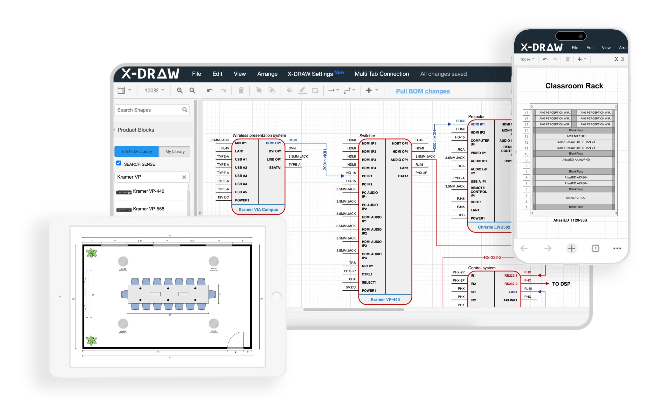
Why X-Draw Leads the FireCAD Alternative Market
X-Draw represents a paradigm shift from traditional fire protection design software by integrating artificial intelligence, cloud-based collaboration, automated documentation, and end-to-end project workflows into a unified platform. Unlike legacy tools that focus solely on drawing creation, X-Draw addresses the complete project lifecycle from initial system design through client proposals, installation documentation, and project management.
Core Capabilities That Make X-Draw the Best FireCAD Alternative
1. Automated Fire System Design Templates
X-Draw provides dedicated Fire System templates enabling engineers and designers to launch fire alarm projects and fire protection layouts immediately without building designs from scratch. These intelligent templates include:
Pre-configured layer structures aligned with industry standards
Symbol libraries for all fire safety devices (detectors, pull stations, strobes, horns)
Standard titleblocks customizable with firm branding
Calculation worksheets for coverage and power analysis
This template automation accelerates project setup while standardizing documentation across teams, ensuring consistency regardless of which engineer initiates the project.
2. Intelligent Floor Plan Creation
The platform supports uploading existing floor plans from architects or creating layouts directly within X-Draw. Designers can accurately place smoke detectors, heat detectors, manual pull stations, notification appliances, and other fire safety devices on building layouts while maintaining organized project documentation.
Smart placement tools include:
Automatic spacing guides ensuring code-compliant device distribution
Coverage visualization showing protected areas in real-time
Snap-to-wall features for accurate mounting locations
Device rotation maintaining proper orientation
3. AI-Powered Design Automation
Unlike traditional CAD-only solutions, X-Draw leverages artificial intelligence to automate design tasks, assist with optimal device placement, and reduce repetitive manual work. The AI engine analyzes:
Building geometry and occupancy classifications
NFPA code requirements for device spacing and coverage
Historical project data from your firm's previous designs
Manufacturer specifications and performance characteristics
This intelligent automation helps teams complete projects 40-60% faster while maintaining consistency across designs and reducing code compliance errors.
4. Cloud-Based Platform Architecture
Being fully cloud-based, X-Draw eliminates software installation headaches, IT infrastructure requirements, and allows users to access projects from anywhere. Benefits include:
Web browser access from any device without downloads
Automatic software updates with no disruption
Centralized project storage accessible to entire teams
Mobile compatibility for on-site work and client meetings
Teams can work remotely while maintaining a centralized source of project data and documentation, essential for modern distributed work environments.
5. Real-Time Team Collaboration
Multiple stakeholders can collaborate on the same project simultaneously, making it easier for engineers, designers, project managers, and installers to stay aligned throughout the project lifecycle. Collaboration features include:
Multi-user editing without file locking or version conflicts
Change tracking showing modifications in real-time
Comment threads for design review and coordination
Role-based permissions controlling access and editing rights
This real-time collaboration eliminates email chains, prevents file version confusion, and accelerates project delivery.
6. Automatic Documentation Generation
X-Draw automatically generates critical project documents, significantly reducing administrative effort and documentation errors:
Bills of Materials (BOM) with accurate quantities, part numbers, and specifications
Technical drawings formatted to professional standards
Project documentation organized by system and phase
Scope of Work documents describing installation requirements
Proposal-ready outputs accelerating sales cycles
Changes to designs automatically update all connected documentation, ensuring synchronized project data throughout the development process.
7. Integrated Proposal & Reporting Tools
Unlike FireCAD-focused solutions that primarily handle drawings, X-Draw connects design workflows with proposal generation and project documentation, allowing teams to move from design to client-ready deliverables faster. The integrated proposal system includes:
Automatic pricing from BOM data and labor estimates
Customizable templates maintaining brand consistency
Professional formatting with graphics and specifications
Digital delivery via secure client portals
This integration eliminates manual data re-entry between design and sales workflows, reducing errors and accelerating quote delivery.
8. Massive Product & Device Library
Users gain access to an extensive database containing over 1.5 million products and devices, helping designers quickly select and incorporate components into fire protection and low-voltage system designs. The library includes:
Current specifications from major manufacturers (Honeywell, Johnson Controls, Siemens, Edwards, Notifier)
Technical drawings and mounting dimensions
Compatible accessories and system components
Pricing data for accurate project estimates
This comprehensive library eliminates time spent researching specifications and creating custom symbols, while ensuring accurate product data in all documentation.
9. BIM and Third-Party Integration
X-Draw supports integration with industry-standard tools and workflows, including BIM environments and data exchange with other design platforms, improving interoperability across projects:
IFC import/export for architect coordination
Revit integration for MEP modeling
DWG/DXF compatibility maintaining AutoCAD workflows
API connections to business systems
These integration capabilities enable X-Draw to fit seamlessly into existing workflows while enhancing collaboration with other project stakeholders.
10. Automated Technical Drawings
The platform can automatically generate comprehensive technical documentation:
Line schematics showing signal paths and system architecture
Signal flow diagrams for troubleshooting and commissioning
Rack elevations displaying equipment mounting and cabling
Floor plans with device layouts and zone boundaries
Technical system drawings formatted to industry standards
This automated drawing generation reduces drafting time by up to 60% while improving design consistency across projects and eliminating manual drafting errors.
11. BOM-to-Drawing Synchronization
X-Draw can transform project BOM data into structured technical drawings, helping ensure that documentation remains synchronized with project specifications and reducing manual coordination work. Key capabilities include:
Bidirectional updates between BOMs and drawings
Quantity verification flagging discrepancies automatically
Device tracking from quote through installation
Change order documentation showing modifications clearly
This synchronization prevents the common disconnect between quoted materials and installed systems.
12. End-to-End Project Workflow
From initial design and engineering through documentation, proposals, collaboration, and project management, X-Draw provides a unified workflow that eliminates the need for multiple disconnected software tools. The complete platform includes:
Design and engineering tools for system layouts
Documentation generation for technical deliverables
Proposal creation for client-facing materials
Project tracking for schedule and resource management
Team collaboration across all project phases
This unified approach reduces software costs, eliminates data re-entry, and improves team productivity across the entire project lifecycle.
Pros
✓ Most comprehensive feature set in the fire protection design market ✓ AI automation dramatically reduces manual work and project completion time ✓ Cloud-based accessibility enables remote work and real-time collaboration ✓ Extensive 1.5M+ device library eliminates manual product research ✓ Automatic documentation minimizes administrative overhead and errors ✓ BIM integration ensures compatibility with modern construction workflows ✓ End-to-end platform eliminates need for multiple disconnected tools ✓ Scalable architecture grows with firm needs and project complexity ✓ Responsive support with dedicated account management
Cons
✗ Premium pricing may exceed budgets for very small firms or solo practitioners ✗ Learning investment required to leverage full feature set ✗ Internet dependency for cloud-based access (though offline mode available)
Best For
Fire protection engineering firms, MEP consultancies, AV system integrators, life safety specialists, and electrical contractors seeking a comprehensive platform that handles the entire project lifecycle from initial system design through client proposals, installation documentation, and project management. Ideal for teams requiring real-time collaboration, AI automation, and extensive integration capabilities.

2. AutoCAD with Fire Protection Add-ons
Overview
AutoCAD remains the most widely recognized CAD platform globally, and when combined with fire protection-specific add-ons, it can serve as a capable FireCAD alternative for engineers and consultants already invested in the Autodesk ecosystem.
Key Features
Industry-standard 2D and 3D drafting capabilities
Extensive third-party add-on ecosystem for fire protection symbols
DWG file format compatibility across the industry
Customizable tool palettes for fire safety devices
Cloud collaboration through Autodesk cloud services
Mobile app support for viewing drawings on-site
Scripting capabilities (AutoLISP, Visual LISP) for workflow automation
Pros
✓ Industry standard format recognized universally ✓ Powerful customization through scripts and plugins ✓ Extensive training resources available globally ✓ Strong BIM integration via Autodesk suite
Cons
✗ Generic platform requiring significant customization for fire protection workflows ✗ Expensive licensing especially for full Autodesk subscriptions ✗ Limited automation compared to purpose-built solutions ✗ Steep learning curve for new users ✗ Manual documentation processes for BOMs and specifications ✗ No fire-specific AI features
Best For
Established engineering firms already using AutoCAD for other disciplines who need occasional fire protection design capabilities and have staff experienced with the platform.
Pricing: Starting at $1,865/year for AutoCAD subscription
3. Revit MEP with Fire Protection Families
Overview
Revit MEP serves as Autodesk's BIM platform for mechanical, electrical, and plumbing systems. With appropriate fire protection families and extensions, it handles fire alarm system modeling within comprehensive building information models.
Key Features
3D BIM modeling with intelligent parametric objects
Fire protection MEP families for devices and equipment
Coordination tools for clash detection with other trades
Automatic schedules generated from BIM data
Cloud collaboration through BIM 360 Docs
Rendering capabilities for client presentations
Quantity takeoff from model elements
Pros
✓ Full BIM functionality for integrated building design ✓ Clash detection prevents coordination errors ✓ Automatic quantity takeoffs from model data ✓ Strong industry adoption in commercial construction
Cons
✗ BIM expertise required beyond simple CAD skills ✗ High software cost for Revit licenses ✗ Resource intensive requiring powerful computers ✗ Overkill for simple 2D projects ✗ Limited fire-specific automation compared to dedicated tools ✗ Longer learning curve than traditional CAD
Best For
MEP engineering firms working on large commercial projects where BIM coordination is required by project delivery methods and full building information modeling justifies the investment.
Pricing: Starting at $2,825/year for Revit subscription
4. BlueBeam Revu
Overview
BlueBeam Revu provides powerful PDF markup and collaboration tools popular with contractors and consultants for project coordination and document management, though it requires separate CAD software for initial drawing creation.
Key Features
PDF markup and annotation tools
Document comparison showing changes between versions
Cloud-based collaboration through Bluebeam Studio
Quantity takeoff tools for estimating
Form creation for standardized documentation
3D PDF support for model viewing
Pros
✓ Excellent collaboration features for project teams ✓ Industry-standard in construction documentation ✓ Powerful markup and review capabilities ✓ Cloud-based project coordination
Cons
✗ Not a design tool – requires separate CAD software ✗ Limited to PDF workflows ✗ No device libraries or fire-specific features ✗ Supplements rather than replaces design software
Best For
Project coordinators, consultants, and contractors needing powerful PDF collaboration alongside primary design software rather than as a standalone FireCAD alternative.
Pricing: Starting at $349/year for Bluebeam Revu Standard
5. DraftSight
Overview
DraftSight provides cost-effective 2D/3D CAD capabilities with familiar AutoCAD-like interface and DWG compatibility, making it an accessible option for system integrators and consultants with budget constraints.
Key Features
DWG file compatibility with AutoCAD
Familiar interface reducing learning curve
2D and 3D drafting capabilities
Cloud storage integration
Customizable tool palettes
PDF export and markup tools
Pros
✓ Lower cost than AutoCAD while maintaining compatibility ✓ Familiar workflow for AutoCAD users ✓ Professional features at accessible price point ✓ Good DWG compatibility for collaboration
Cons
✗ Generic CAD tool lacking fire-specific features ✗ Manual documentation processes ✗ Limited automation compared to specialized platforms ✗ Smaller ecosystem of add-ons than AutoCAD ✗ No built-in device libraries for fire protection ✗ No AI features
Best For
Small to medium firms seeking AutoCAD-like functionality at lower cost who can customize workflows for fire protection design needs and don't require advanced automation.
Pricing: Starting at $499/year for DraftSight Premium
6. SketchUp Pro
Overview
SketchUp Pro offers intuitive 3D modeling capabilities popular for architectural visualization that, with appropriate plugins, can support basic fire protection layout planning and client presentations.
Key Features
Intuitive 3D modeling interface
Component libraries for repeated elements
Plugin ecosystem (Extension Warehouse)
3D Warehouse for shared models
LayOut for 2D documentation
Rendering capabilities for presentations
Pros
✓ Easy to learn with short training curve ✓ Good visualization for client presentations ✓ Active plugin community expanding capabilities ✓ Free version available for basic use (SketchUp Free)
Cons
✗ Not purpose-built for technical documentation ✗ Limited precision compared to engineering CAD ✗ Manual documentation required ✗ Few fire-specific plugins available ✗ Not ideal for detailed technical drawings
Best For
Design-build firms needing 3D visualization for client presentations alongside other technical tools for detailed engineering documentation.
Pricing: SketchUp Pro: $349/year
FireCAD vs XTEN-AV X-Draw Comparison Table
Feature | Traditional FireCAD | XTEN-AV X-Draw |
AI Design Automation | ✗ Manual processes | ✓ Advanced AI assistance for placement and optimization |
Cloud Collaboration | ✗ Desktop-only | ✓ Real-time multi-user cloud platform |
Device Library Size | Limited to included symbols | 1.5M+ products with specifications |
Automatic BOM Generation | Manual creation | ✓ Auto-generated and synchronized with drawings |
Proposal Integration | ✗ Separate software required | ✓ Built-in proposal generation tools |
BIM Integration | Limited or add-on required | ✓ Full BIM compatibility and IFC support |
Technical Drawing Automation | Manual drafting | ✓ Auto-generates schematics, diagrams, elevations |
Learning Curve | Steep, CAD-focused | Moderate with intuitive templates |
Mobile Access | ✗ Desktop installation required | ✓ Cloud-based access from any device |
Team Collaboration Tools | Email/file sharing | ✓ Real-time collaboration with change tracking |
Documentation Automation | Manual Word/Excel documents | ✓ Auto-generated scope, specs, proposals |
Project Management | ✗ External tools needed | ✓ Integrated project workflow management |
Software Updates | Periodic, manual installation | ✓ Automatic cloud updates |
Data Backup | Manual user responsibility | ✓ Automatic cloud backup |
Scalability | Per-seat licensing constraints | ✓ Flexible cloud-based scaling |
Support Model | Limited technical support | ✓ Dedicated account management |
Total Cost of Ownership | High (license + customization + time) | Optimized (automation + integration + efficiency) |
Best Use Case | Traditional desktop CAD workflows | Modern cloud-based integrated project delivery |
Frequently Asked Questions
What is the best FireCAD alternative for small engineering firms?
For small engineering firms with 2-5 team members, XTEN-AV X-Draw offers the best value proposition despite premium pricing. The AI automation and automatic documentation generation reduce project completion time by 40-60%, effectively increasing firm capacity without adding staff. The cloud-based collaboration eliminates IT infrastructure costs, while the 1.5M+ device library prevents time waste on product research. When calculating total cost of ownership including time savings, X-Draw typically delivers positive ROI within the first year for active firms completing 15+ fire protection projects annually.
For firms with extremely limited budgets completing fewer than 10 projects yearly, DraftSight provides basic CAD functionality at lower subscription cost, though without automation benefits.
Can XTEN-AV X-Draw replace multiple software tools in our workflow?
Yes. X-Draw is specifically designed as an end-to-end platform replacing multiple disconnected tools commonly used by fire protection firms:
Replaces traditional CAD (AutoCAD, DraftSight) for drawing creation
Eliminates proposal software (separate quoting tools) with integrated proposal generation
Removes separate BOM tools (Excel spreadsheets) with automatic synchronized BOMs
Replaces documentation software (Word, separate spec writers) with auto-generated technical documents
Reduces project management tools with integrated workflow tracking
This unified platform approach reduces software subscription costs while eliminating data re-entry between systems, improving accuracy and efficiency. Most firms find the consolidated workflow significantly more productive than managing multiple specialized tools.
How does AI improve fire protection design in X-Draw?
Artificial intelligence in X-Draw delivers multiple productivity enhancements:
Device Placement Optimization: The AI analyzes building geometry, occupancy classifications, and NFPA code requirements to suggest optimal placement for smoke detectors, notification appliances, and other fire safety devices. This ensures code compliance while minimizing unnecessary device count.
Coverage Validation: AI continuously checks coverage areas as you design, alerting you to gaps or overlaps before drawings are complete, preventing costly rework.
Product Recommendations: Based on project specifications, environmental conditions, and historical data, the AI recommends appropriate devices from the 1.5M+ library, considering compatibility, performance, and budget constraints.
Design Consistency: The AI learns from your firm's previous projects, suggesting placement patterns and design approaches that match your established standards, ensuring consistency across team members.
Automated Documentation: AI extracts data from designs to automatically generate accurate BOMs, specifications, and scope documents, eliminating manual transcription errors.
These AI capabilities reduce design time by 40-60% while improving accuracy and code compliance compared to manual approaches.
Is cloud-based fire protection design software secure?
Yes. Modern cloud-based platforms like XTEN-AV X-Draw employ enterprise-grade security measures that typically exceed the protection of desktop software stored on individual computers:
Data Encryption: All data transmission uses TLS encryption, while stored data employs AES-256 encryption, meeting financial industry security standards.
Access Controls: Role-based permissions ensure team members access only appropriate project data, with multi-factor authentication preventing unauthorized access.
Automatic Backups: Cloud platforms maintain redundant backups across multiple data centers, eliminating risks of data loss from hardware failure, theft, or local disasters that threaten desktop installations.
Security Certifications: Reputable platforms maintain SOC 2, ISO 27001, or similar certifications demonstrating adherence to rigorous security frameworks.
Audit Trails: Comprehensive logging tracks all access and modifications, supporting forensic analysis if needed.
Disaster Recovery: Geographic redundancy ensures service continuity even if entire data centers fail.
When evaluating cloud platforms, request security documentation and verify certifications meet your firm's requirements and client expectations.
How long does it take to transition from FireCAD to X-Draw?
Transition timelines vary based on team size and project complexity:
Individual Users: 1-2 weeks to become productive with basic features; 4-6 weeks for full platform mastery
Small Teams (2-5 people): 3-4 weeks for team onboarding with staggered training; 6-8 weeks for complete workflow integration
Large Teams (6+ people): 6-8 weeks for phased rollout; 3-6 months for organization-wide standardization
Best practices for smooth transition:
Start with new projects rather than migrating active work
Designate power users who train teammates after mastering the platform
Leverage XTEN-AV training resources including video tutorials and webinars
Maintain legacy software access during transition for reference
Schedule dedicated training time rather than learning while under project deadlines
Most teams report full productivity within 4-8 weeks, with many experiencing improved efficiency compared to previous workflows even during the learning phase due to automation benefits.
Does X-Draw work for both fire alarm and fire sprinkler design?
Yes. XTEN-AV X-Draw supports comprehensive fire protection system design including:
Fire Alarm Systems:
Smoke and heat detector placement and coverage
Manual pull station positioning
Notification appliance layouts (horns, strobes, speakers)
Panel and NAC circuit design
Addressable system device addressing
Signal flow diagrams and wiring schematics
Fire Sprinkler Systems:
Sprinkler head placement and spacing
Pipe routing and sizing
Hydraulic calculations integration
Valve and component specifications
Backflow preventer locations
System riser diagrams
Integrated Life Safety Systems:
Mass notification system coordination
Emergency voice communication
Fire pump specifications
Emergency lighting integration
The platform's extensive device library includes products from all major fire alarm and sprinkler manufacturers, supporting comprehensive fire protection engineering workflows.
What training and support does XTEN-AV provide for X-Draw?
XTEN-AV offers comprehensive training and support resources:
Onboarding Programs:
Live training sessions tailored to team experience levels
Recorded video tutorials covering common workflows
Sample projects for hands-on practice
Quick start guides for immediate productivity
Ongoing Support:
Dedicated account managers for enterprise clients
Technical support via phone, email, and chat
Screen sharing for complex troubleshooting
Knowledge base with searchable articles
Community Resources:
User forums for peer-to-peer assistance
Regular webinars showcasing new features and best practices
Newsletter updates with tips and industry insights
Custom Training:
On-site training available for large teams
Workflow consulting optimizing firm-specific processes
Custom template development matching firm standards
This comprehensive support infrastructure ensures teams maximize platform value while minimizing learning curves and productivity disruptions.
Conclusion
Selecting the right FireCAD alternative for your engineering firm, consultancy, or system integration business represents a strategic decision impacting project efficiency, team collaboration, and competitive positioning in 2026's demanding fire protection market.
XTEN-AV X-Draw emerges as the clear leader among FireCAD alternative software by delivering comprehensive capabilities that traditional CAD tools cannot match. The platform's AI-powered automation, extensive 1.5M+ device library, cloud-based collaboration, and end-to-end project workflows address the complete needs of modern fire protection professionals—from initial system design through client proposals, installation documentation, and project management.
For engineers, consultants, and system integrators prioritizing productivity, accuracy, and scalability, investing in purpose-built platforms like X-Draw delivers measurable returns through:
40-60% reduction in design and documentation time
Elimination of multiple software subscriptions through integrated workflows
Improved accuracy with synchronized BOMs and automated documentation
Enhanced collaboration enabling distributed teams to work seamlessly
Faster project delivery increasing firm capacity and revenue potential
While budget-conscious firms may consider mid-tier options like DraftSight or leverage existing AutoCAD investments, these approaches require accepting manual workflows, limited automation, and integration challenges that ultimately constrain growth and efficiency.
The fire protection industry continues its rapid evolution toward cloud-based, AI-enhanced platforms that unify design, documentation, and project management into seamless workflows. Firms adopting these next-generation tools position themselves for sustainable competitive advantage while those clinging to legacy systems face increasing efficiency gaps and market pressure.
Ready to transform your fire protection design workflow? Discover how XTEN-AV X-Draw can accelerate your projects, reduce documentation time, and enhance team productivity. Schedule a personalized demo today to experience the future of fire protection engineering and see firsthand why leading consultants and system integrators are making X-Draw their FireCAD alternative of choice.
AV Network Setup Best Practices for Large Enterprise Installations
What are the best practices for deploying large-scale enterprise AV networks that support thousands of endpoints across multiple buildings while maintaining security, reliability, and performance? The answer: Implement hierarchical three-tier network architecture, deploy functional VLAN segmentation with comprehensive QoS policies, establish redundant infrastructure with automatic failover, integrate AI-powered monitoring and automation, enforce zero-trust security models, and maintain meticulous documentation of all network components—creating a robust foundation that scales seamlessly from hundreds to thousands of collaboration spaces.
Planning enterprise AV networks shares fundamental principles with residential installations but operates at exponentially greater scale and complexity. Just as a carefully designed ethernet house wiring diagram maps every connection in a home—documenting switch locations, cable runs, patch panel configurations, and device placements—enterprise deployments require comprehensive documentation of network topology, VLAN architecture, IP addressing schemes, routing policies, and security boundaries spanning entire campuses. Understanding Home Network Wiring concepts including structured cabling standards, network hierarchy, traffic segmentation, and bandwidth allocation provides the foundational knowledge necessary for architecting mission-critical AV infrastructure supporting business operations across global organizations.
For AV integrators, enterprise architects, and technology consultants designing large-scale unified communications platforms, success depends on mastering network engineering principles, cybersecurity best practices, automation frameworks, and operational excellence methodologies. This comprehensive guide provides battle-tested strategies, architectural patterns, implementation procedures, and management frameworks for building world-class enterprise AV networks that deliver exceptional user experiences, maintain 99.99% uptime, and adapt seamlessly to evolving business requirements and emerging technologies.
Key Takeaways
Enterprise AV networks require three-tier hierarchical architecture (access, distribution, core) supporting 500-10,000+ endpoints
Best-practice VLAN design separates traffic by function (video, audio, control, management) improving performance 60-80%
Redundancy at every layer with automatic failover ensures 99.99% uptime for business-critical communications
Comprehensive QoS policies across all network layers prioritize real-time AV traffic preventing degradation
Automation and orchestration reduce deployment time by 70% and configuration errors by 90%
Zero-trust security architecture with micro-segmentation reduces breach impact by 80%+
AI-powered monitoring detects 85% of potential failures before user impact through predictive analytics
Proper bandwidth planning accounts for simultaneous peak usage plus 50-100% growth buffer
Multicast optimization through IGMP snooping and PIM reduces bandwidth consumption by 90%
Documentation standards are critical—comprehensive records reduce MTTR by 70%
Change management processes prevent 95% of human-error outages in production networks
Lifecycle planning for 5-7 year technology refresh cycles protects infrastructure investments
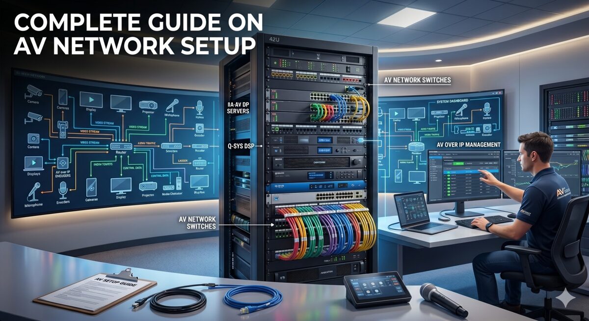
What Is an AV Network Setup?
An AV network setup in enterprise environments is a comprehensive, IP-based infrastructure designed to transport audio signals, video streams, control data, and management traffic for audiovisual systems across converged Ethernet networks using standard networking protocols—replacing traditional point-to-point AV cabling with flexible, scalable, and centrally-managed network-based distribution supporting thousands of simultaneous users.
Defining Large Enterprise AV Networks
Scale Characteristics:
Endpoint Density:
500-1,000 endpoints: Mid-size enterprise (50-100 buildings or single large campus)
1,000-5,000 endpoints: Large enterprise (multiple campuses, regional offices)
5,000-10,000+ endpoints: Global enterprise (worldwide operations, distributed workforce)
Geographic Distribution:
Multi-building campuses spanning 100-1,000+ acres
Metropolitan deployments across city or region
National networks connecting offices nationwide
Global infrastructure supporting international operations
Service Complexity:
Unified communications: Video conferencing, voice, messaging, presence
Collaboration platforms: Wireless presentation, content sharing, whiteboarding
Digital workplace: Room scheduling, wayfinding, building automation integration
Content distribution: IPTV, digital signage, emergency communications
Production facilities: Broadcast studios, training centers, auditoriums
Enterprise AV Network Architecture Layers
Physical Infrastructure Layer:
Structured Cabling System:
Horizontal cabling: Cat6a/Cat7 supporting 10GBASE-T to every endpoint
Backbone cabling: Single-mode fiber for building-to-building (1-10km)
Multimode fiber: OM4 for intra-building distribution (300-550m at 10-100 Gbps)
Cable pathways: Conduit, cable trays, risers supporting current and future capacity
Patch panels: High-density termination in IDFs/MDFs with comprehensive labeling
Testing standards: TIA/EIA-568 certification for all permanent links
Network Equipment:
Access switches: 500-2,000 units (24-48 ports each, PoE++, Layer 2/3)
Distribution switches: 50-200 units (48-port + uplinks, full Layer 3 routing)
Core switches: 4-20 units (chassis-based or fixed, 1-10 Tbps capacity)
Wireless infrastructure: Enterprise WiFi 6E/7 for mobile collaboration
Network services: DHCP, DNS, NTP, RADIUS, multicast rendezvous points
Logical Architecture Layer:
VLAN Design:
50-500 VLANs total across enterprise (depending on segmentation strategy)
Functional VLANs: Separate video, audio, control, conferencing, wireless, signage
Geographic VLANs: Building or floor-specific when appropriate
Security zones: Trusted, semi-trusted, guest, management VLANs
Service VLANs: Infrastructure, monitoring, backup, and maintenance networks
IP Addressing Strategy:
Private IP space allocation: /8 or /12 for enterprise (10.0.0.0/8 or 172.16.0.0/12)
Hierarchical subnetting: Building, floor, function-based address blocks
DHCP with reservations: Predictable addressing for known AV devices
IPv6 readiness: Dual-stack or IPv6-only for future-proofing
Routing and Switching:
Dynamic routing protocols: OSPF, EIGRP, or BGP for scalability
Redundant paths: ECMP (Equal-Cost Multi-Path) for load balancing
Fast convergence: Sub-second failover with proper tuning
Route summarization: Reducing routing table size and update traffic
AV Application Layer:
Video Conferencing Infrastructure:
1,000-5,000 conference rooms equipped with AV systems
Room systems: Zoom Rooms, Microsoft Teams Rooms, Cisco Webex, Poly
Meeting room configurations: Huddle (2-6 people), standard (6-12), large (12-30), boardroom (30+)
Hybrid capabilities: In-room and remote participants seamlessly integrated
AV-over-IP Distribution:
Encoders/decoders: 2,000-10,000 devices for video distribution
Technology mix: SDVoE for low-latency, compressed IP for general use
Multicast distribution: One-to-many streaming reducing bandwidth
Video walls: Large-format displays in operations centers, lobbies, training facilities
Audio Infrastructure:
Dante networking: 5,000-20,000 audio channels distributed
DSP processors: Room combining, zoned paging, background music
Microphones and speakers: Ceiling arrays, boundary mics, line arrays
Emergency communications: Life safety integration with fire alarm systems
Control and Management:
Centralized platforms: Crestron Fusion, Extron GlobalViewer, Q-SYS Cloud
Room controllers: Touch panels, mobile apps, voice assistants
Automation: Scheduling, occupancy-based control, energy management
Analytics: Utilization tracking, performance monitoring, ROI reporting
Enterprise vs Traditional AV Infrastructure
Legacy Point-to-Point Model:
Dedicated AV cabling: HDMI, SDI, coax for each signal path
Matrix switchers: Fixed input/output configurations requiring replacement to scale
Isolated systems: Separate networks for AV, IT, building automation
Manual management: Configuration, troubleshooting, and changes all manual
Limited scalability: Major infrastructure overhaul required for expansion
Modern Network-Based Model:
Converged infrastructure: AV, IT, IoT sharing common network
Software-defined routing: Any source to any destination via configuration
Centralized management: Single pane of glass visibility and control
Automated provisioning: New rooms deployed in hours instead of days
Unlimited scalability: Add capacity by deploying additional network resources
Why Enterprise AV Network Design Matters
Business Continuity and Productivity
Mission-Critical Communications: Modern enterprises depend on networked AV systems for core operations:
Executive Leadership:
All-hands meetings to 10,000+ employees simultaneously
Board presentations with confidential financial information
Crisis management during emergencies or incidents
Investor relations quarterly earnings calls and presentations
Operational Functions:
Customer support centers with video assistance
Sales presentations to prospects and clients
Training delivery to distributed workforce
Remote work enablement for hybrid teams
Financial Impact of Downtime:
Outage Scope | Affected Users | Hourly Cost | Daily Cost |
Single room | 5-15 | $500-1,500 | $4K-12K |
Floor/building | 50-500 | $5K-50K | $40K-400K |
Campus-wide | 500-5,000 | $50K-500K | $400K-4M |
Enterprise-wide | 5,000-50,000 | $500K-5M | $4M-40M |
Downtime calculations based on: |
Lost productivity: $50-100/hour per affected employee
Revenue impact: Failed customer meetings, delayed deals
Reputation damage: Client confidence, employee morale
Recovery costs: Emergency support, expedited replacements
Security and Compliance Imperatives
Regulatory Requirements:
Healthcare Organizations (HIPAA):
Telemedicine platforms require encryption and audit logging
Network segmentation separating PHI-handling systems from general network
Access controls limiting who can view patient information
Business associate agreements covering AV vendors and integrators
Financial Services (PCI-DSS, SOX, GLBA):
Trading floor communications must be monitored and recorded
Network isolation for cardholder data environments
Executive communications require confidentiality protections
Audit trails for all access to sensitive financial systems
Education (FERPA):
Lecture capture systems handling student educational records
Video surveillance integration with campus security
Remote learning platforms protecting student privacy
Government and Defense (FISMA, ITAR):
Classified information handling in secure conference facilities
TEMPEST requirements for electromagnetic shielding
Access restrictions based on clearance levels
Encryption standards for all communications
Zero-Trust Security Framework:
Micro-Segmentation:
VLAN-level isolation for every functional group
ACLs enforcing least-privilege access between segments
Application-aware firewalling controlling specific traffic types
Private VLANs preventing lateral movement within segments
Continuous Verification:
802.1X authentication for all devices joining network
Certificate-based security replacing static passwords
Posture assessment before granting network access
Behavioral analytics detecting anomalous activity
Assumed Breach Mentality:
Network monitoring on all segments detecting intrusions
Automated response quarantining compromised devices instantly
Incident response playbooks tested regularly
Forensic capabilities for post-incident analysis
Return on Investment and Total Cost of Ownership
Infrastructure Investment:
Capital Expenditure (CapEx):
Network infrastructure: $500K-5M (switches, cabling, racks)
AV endpoints: $2M-20M (cameras, displays, codecs, processors)
Management platforms: $100K-1M (software licenses, servers)
Professional services: $500K-3M (design, installation, commissioning)
Total initial investment: $3M-29M typical range
Operational Expenditure (OpEx):
Support staffing: $300K-3M annually (AV engineers, network admins)
Maintenance contracts: $200K-2M annually (vendor support, warranties)
Bandwidth costs: $50K-500K annually (Internet, WAN links)
Software licensing: $50K-500K annually (management platforms, updates)
Total annual operations: $600K-6M typical range
ROI Calculation:
Productivity Gains:
Travel reduction: $2M-20M annually (fewer on-site meetings required)
Faster decision-making: $1M-10M annually (real-time collaboration across locations)
Recruitment advantages: $500K-5M annually (broader talent pool with remote work)
Real estate optimization: $1M-10M annually (hoteling, shared spaces vs dedicated offices)
Payback Period: Most enterprise AV networks achieve payback in 18-36 months through combination of productivity gains, travel savings, and real estate optimization.
TCO Over 5 Years:
Example Enterprise (1,000 rooms):
Initial Investment: $10M
Annual Operations: $2M × 5 years = $10M
Technology Refresh (Year 5): $3M
Total 5-Year TCO: $23M
Per-Room TCO: $23,000 over 5 years = $4,600/year/room
Cost Avoidance: Proper design prevents:
Rework: 30-40% of project cost if infrastructure undersized
Emergency fixes: 5-10x normal cost for after-hours troubleshooting
Security breaches: $100K-10M+ per incident average cost
Premature replacement: Well-designed systems last 7-10 years vs 3-5 for poor designs
Common Challenges in Large Enterprise AV Installations
Challenge 1: Managing Configuration Complexity at Scale
The Complexity Problem:
Configuration Volume:
500-2,000 network switches each requiring configuration
5,000-20,000 switch ports with VLAN, QoS, PoE settings
1,000-5,000 AV endpoints needing IP addresses, firmware, settings
50-500 VLANs propagated across infrastructure
1,000+ ACL rules controlling inter-VLAN traffic
Configuration Drift: Without automation, manual changes accumulate:
Switch configurations diverge from standards over time
VLAN assignments become inconsistent across sites
QoS policies applied differently on various switches
Security settings weakened by expedient "temporary" changes
Documentation becomes outdated and unreliable
Solutions:
Infrastructure as Code (IaC):
Ansible/Terraform Approach:
1. Configuration Templates:
- Switch base configuration
- VLAN definitions
- QoS policies
- ACL rules
- Port configurations by device type
2. Variable Files:
- Site-specific parameters
- IP address allocations
- Device inventories
3. Automated Deployment:
- Push configurations to all switches
- Verify deployment success
- Rollback on errors
4. Version Control:
- Git repository for all configs
- Change tracking and audit trail
- Peer review before deployment
Benefits:
Consistency: All switches configured identically
Repeatability: Deploy 100 switches as easily as 1
Speed: Configure entire building in minutes
Validation: Automated testing before production
Documentation: Code IS the documentation
Configuration Management Platforms:
Cisco DNA Center: Intent-based networking, automated provisioning
Aruba Central: Cloud-based management for Aruba infrastructure
Ansible Tower/AWX: Open-source automation with enterprise features
NetBox: Network documentation and IPAM (IP Address Management)
Challenge 2: Ensuring Consistent QoS Across Multi-Vendor Equipment
Multi-Vendor Environments: Enterprise networks rarely use single vendor:
Typical Vendor Mix:
Network switches: Cisco, Aruba, Juniper mixed across sites
AV endpoints: Crestron, Extron, Shure, Biamp, various room system vendors
Wireless: Cisco, Aruba, Ruckus access points
Security: Palo Alto, Fortinet, Cisco firewalls
QoS Inconsistency Problems:
DSCP markings: Different defaults per vendor
Queue mappings: Varied interpretations of priority levels
Trust boundaries: Where to trust/remark packets differs
Bandwidth allocation: Different methods and granularity
Solutions:
Standardized QoS Framework:
Step 1: Define Enterprise-Wide Policy
Enterprise QoS Standard:
Traffic Class | DSCP | 802.1p | Queue | BW % | Latency
--------------|------|--------|-------|------|--------
Network Control | CS6 | 7 | Q1 | 5% | <1ms
Real-time Audio | EF | 5 | Q2 | 20% | <10ms
Real-time Video | AF41 | 4 | Q3 | 30% | <20ms
Control Systems | AF31 | 3 | Q4 | 10% | <50ms
Wireless Pres | AF21 | 2 | Q5 | 15% | <100ms
Best Effort | DF | 0 | Q6 | 20% | Best effort
Step 2: Configure Trust Boundaries
AV devices: Trust DSCP markings from known devices (via 802.1X or MAC list)
User devices: Don't trust; classify and mark at network edge
Between switches: Preserve DSCP through trunk links
Step 3: Vendor-Specific Implementation
Cisco Implementation:
- class-map match-any REAL-TIME-AUDIO
- match dscp ef
- policy-map ENTERPRISE-AV-QOS
- class REAL-TIME-AUDIO
- priority percent 20
Aruba Implementation:
- qos dscp-map default
- qos trust dscp
- qos queue-profile ENTERPRISE-AV
Step 4: End-to-End Testing
Packet captures verifying DSCP preservation
iPerf tests with DSCP marking confirming bandwidth allocation
Real AV traffic monitoring during peak usage
Regular audits ensuring policy compliance
Challenge 3: Multicast Scalability
Enterprise Multicast Challenges:
Scale Issues:
10,000+ multicast groups across enterprise (each AV stream is a group)
IGMP state table limitations on switches (512-4,096 groups typically)
PIM neighbor relationships consuming CPU on routers
Multicast forwarding state memory limitations
Rendezvous Point becoming bottleneck
Symptom: Multicast Meltdown
AV streams suddenly stop reaching destinations
Switch CPU spikes to 100%
Network instability affecting all traffic
Recovery requires switch reboot, causing broader outage
Solutions:
Multicast Design Best Practices:
IGMP Optimization:
Per-VLAN Configuration:
interface Vlan100
description AV-VIDEO-DISTRIBUTION
ip address 10.100.0.1 255.255.0.0
ip pim sparse-mode
ip igmp version 3
ip igmp snooping querier
ip igmp query-interval 60
ip igmp query-max-response-time 10
ip igmp last-member-query-interval 1000
ip igmp immediate-leave
Source-Specific Multicast (SSM):
IGMPv3 required: Supports (S,G) joins instead of (*,G)
Eliminates RP: Source-based trees from beginning
Address range: 232.0.0.0/8 reserved for SSM
Better security: Only specific source can send to group
Reduced state: No (*,G) state consuming resources
Anycast RP for Redundancy:
Multiple Rendezvous Points:
RP1 (10.0.0.10) and RP2 (10.0.0.11) both configured as:
ip pim rp-address 10.0.0.100
MSDP peering between RPs:
ip msdp peer 10.0.0.11 connect-source Loopback0
ip msdp originator-id Loopback0
Result: 10.0.0.100 Anycast RP reachable via either RP1 or RP2
Multicast Boundaries:
Prevent Unwanted Propagation:
interface Vlan200
description USER-DATA-NETWORK
ip multicast boundary BLOCK-AV-MULTICAST
ip access-list standard BLOCK-AV-MULTICAST
deny 239.0.0.0 0.255.255.255
permit any
Capacity Planning:
Switch selection: Verify multicast group table capacity (4,096+ for AV use)
PIM scalability: Distribution layer switches as RPs, not access
SSM migration: Move to SSM for large deployments (>1,000 groups)
Monitoring: Track multicast state consumption, alert at 70% capacity
Challenge 4: Security at Enterprise Scale
Attack Surface Expansion:
Vulnerable Endpoints:
10,000+ AV devices: Many running embedded Linux with rare patches
Hundreds of switches: Each a potential pivot point for attackers
Unknown devices: Shadow IT AV equipment without IT approval
Legacy systems: Equipment no longer receiving security updates
Supply chain risks: Compromised devices shipped from factory
Real-World Enterprise Risks:
Botnet Recruitment:
Mirai-style attacks: Compromised AV devices participating in DDoS
Cryptomining: Stolen CPU cycles from control processors
Data exfiltration: Conference room cameras streaming to attackers
Lateral movement: Compromised codec used to attack financial systems
Recent Incidents (2024-2026):
Fortune 500 manufacturer: Ransomware entered via compromised AV codec
Global bank: Unauthorized recording of executive meetings
Healthcare system: Patient data accessed via meeting room system
University: 5,000 cameras recruited into botnet for DDoS
Solutions:
Zero-Trust Architecture for AV:
Network Micro-Segmentation:
Granular VLAN Strategy:
Instead of: VLAN 100 for all AV (5,000 devices)
Deploy:
- VLAN 100: Executive boardrooms (50 devices)
- VLAN 101: Standard conference rooms Building 1 (200 devices)
- VLAN 102: Standard conference rooms Building 2 (200 devices)
- VLAN 103: Training rooms (100 devices)
- VLAN 104: Digital signage (500 devices)
ACLs between VLANs:
- Deny by default
- Permit only required traffic
- Log all denied traffic
Device Authentication:
802.1X with Certificates:
1. Certificate Authority deployed
2. Each AV device receives unique certificate
3. RADIUS server authenticates via certificate
4. Dynamic VLAN assignment based on device type
5. Periodic re-authentication (every 4-24 hours)
Benefits:
- No shared passwords
- Impossible to spoof device identity
- Automated quarantine of non-compliant devices
- Certificate revocation for compromised devices
Continuous Monitoring:
Behavioral analytics: Detect unusual traffic patterns
Vulnerability scanning: Weekly automated scans of all AV devices
Patch management: Automated firmware updates during maintenance windows
Threat intelligence: IoCs (Indicators of Compromise) fed to IDS/IPS
Automated Response:
Security Orchestration:
1. Anomaly Detected:
- Device sending data to unusual destination
- Port scan detected from AV device
- Unauthorized protocol (BitTorrent, IRC)
2. Automated Actions:
- Isolate device to quarantine VLAN
- Alert SOC (Security Operations Center)
- Create incident ticket
- Capture forensic data (packet capture, logs)
- Notify affected business units
3. Investigation and Remediation:
- SOC analyst reviews evidence
- Device reimaged or replaced
- Root cause analysis
- Update prevention measures
Challenge 5: Maintaining Performance During Growth
Capacity Exhaustion:
Common Bottlenecks:
Trunk saturation: Uplinks between floors/buildings at 100% utilization
Switch oversubscription: Too many ports sharing limited backplane capacity
PoE budget depletion: No power available for additional devices
DHCP exhaustion: IP address space full
Multicast capacity: Tables full, dropping new streams
Symptoms:
Video quality degradation: Progressive worsening over weeks/months
Inconsistent performance: Some rooms work fine, others struggle
Time-based issues: Problems during peak usage (9-11 AM, 1-3 PM)
Building-specific: One building affected while others normal
Solutions:
Proactive Capacity Management:
Monitoring and Forecasting:
Monitoring and Forecasting:
Key Metrics to Track:
1. Bandwidth Utilization:
- Per-trunk link utilization (alert at 70%, critical at 85%)
- Per-VLAN bandwidth consumption
- Peak vs average utilization patterns
- Growth rate (month-over-month)
2. Port Density:
- Available ports per switch
- Port utilization percentage
- Projected exhaustion date
3. PoE Budget:
- Total consumption vs capacity
- Per-port draw
- Peak simultaneous usage
- Growth trend
4. IP Address Space:
- Used vs available IPs per VLAN
- Allocation rate
- Projected exhaustion
5. Multicast State:
- Active groups per switch
- Table utilization percentage
- Growth rate
Capacity Planning Process:
Quarterly Capacity Review:
1. Collect Current Metrics:
- Switch port utilization reports
- Bandwidth utilization graphs
- PoE consumption data
- IP address allocation reports
2. Analyze Growth Trends:
- Calculate monthly growth rate
- Project 6-month and 12-month capacity needs
- Identify resource constraints approaching limits
3. Plan Proactive Upgrades:
- Order equipment with 3-6 month lead time
- Schedule installation during maintenance windows
- Budget approval for capital expenditures
4. Document and Communicate:
- Update capacity forecast models
- Report to leadership
- Coordinate with facilities for new construction
Oversubscription Management:
Access Layer Design:
Bad: 48-port 1 Gbps switch with single 1 Gbps uplink
Oversubscription: 48:1
Good: 48-port 1 Gbps switch with dual 10 Gbps uplinks
Oversubscription: 2.4:1 (acceptable for most AV use)
Distribution Layer Design:
Bad: 10 Gbps ports with 10 Gbps uplinks to core
Oversubscription: Can reach 10:1 or worse
Good: 10 Gbps ports with 40 Gbps uplinks to core
Oversubscription: 2.5:1 or better
Core Layer:
Ideal: Non-blocking architecture (no oversubscription)
All ports can transmit at full speed simultaneously
Best Practices for AV Network Setup in Large Enterprise Environments
Best Practice 1: Hierarchical Network Design
Three-Tier Architecture:
Access Layer (Edge):
Purpose: Connect end-user devices and AV endpoints
Equipment Specifications:
Switch type: Stackable or standalone managed switches
Port count: 24 or 48 ports per switch
Port speed: 1 Gbps copper (10 Gbps for high-bandwidth rooms)
PoE capability: 802.3bt PoE++ (60-100W per port)
Total PoE budget: 740W-1440W per switch minimum
Uplinks: Dual 10 Gbps SFP+ to distribution layer
Features: Layer 2/3, IGMP snooping, QoS, VLANs, PoE management
Deployment Pattern:
Access Switch Placement:
Small Building (<100 rooms):
- 1-3 access switches per floor
- 5-10 switches total
Medium Building (100-300 rooms):
- 3-8 access switches per floor
- 20-50 switches total
Large Campus (300-1,000 rooms):
- 50-200 access switches across campus
- IDF closets every 100m (copper distance limit)
Distribution Layer (Aggregation):
Purpose: Aggregate access layer switches, provide inter-VLAN routing, enforce policies
Equipment Specifications:
Switch type: Modular chassis or high-density fixed
Port density: 48+ ports for access switch uplinks
Port speed: 10 Gbps for access connections, 40 Gbps uplinks to core
Switching capacity: 1-2 Tbps non-blocking
Routing: Full Layer 3 with OSPF, EIGRP, or BGP
Redundancy: Stacked, VSS, or VPC configuration
Services: DHCP, first-hop redundancy (HSRP/VRRP), PIM RP
Design Considerations:
Redundancy Design:
Dual Distribution Switches per Building:
- Access switches dual-homed to both distribution switches
- LACP bundles for bandwidth aggregation + redundancy
- Sub-second failover on link/switch failure
- No single point of failure
Geographic Distribution:
- 1 distribution pair per building or large floor
- Supports 500-2,000 access ports per pair
Core Layer (Backbone):
Purpose: High-speed interconnection between buildings, WAN connectivity, minimal latency
Equipment Specifications:
Switch type: Chassis-based with redundant supervisors and power
Port speed: 40 Gbps, 100 Gbps, or 400 Gbps
Switching capacity: 5-25 Tbps per chassis
Latency: <1 microsecond port-to-port
Redundancy: Full hardware redundancy (supervisors, fabric, power)
Protocols: BGP for WAN, OSPF/EIGRP for campus
Topology Options:
Small Enterprise (1-3 buildings):
- 2 core switches in full mesh
- Collapsed core/distribution for small sites
Large Enterprise (4-20 buildings):
- 2-4 core switches in full or partial mesh
- Geographically distributed for disaster recovery
Global Enterprise (20+ buildings):
- Regional core sites with interconnection
- Hierarchical routing between regions
Why Three-Tier Matters:
Scalability Benefits:
Add buildings: Deploy new access/distribution, connect to core
Add floors: Deploy access switches, connect to distribution
Add rooms: Connect to nearby access switch
Performance Benefits:
Localized failure impact: Access switch failure affects single floor only
Optimized traffic flows: Local traffic stays local, inter-site via core
Predictable latency: Deterministic hop count between endpoints
Operational Benefits:
Clear troubleshooting: Isolate issues to specific layer
Role-based expertise: Access layer team vs core network team
Change management: Upgrades staged by layer reducing risk
Best Practice 2: Comprehensive Documentation Standards
Documentation Philosophy: "If it's not documented, it doesn't exist."
Network Architecture Documentation:
High-Level Design Documents:
Contents:
1. Executive Summary
- Project scope and objectives
- Architecture overview
- Key design decisions and rationale
2. Physical Topology
- Building connectivity diagram
- Equipment rack locations
- Cable pathway maps
- Power distribution
3. Logical Architecture
- VLAN design and numbering
- IP addressing scheme
- Routing design (protocols, areas, summarization)
- Multicast architecture (PIM, RP placement)
4. Security Architecture
- Trust zones and boundaries
- Firewall rules and ACLs
- Authentication and authorization
- Monitoring and logging
5. QoS Design
- Classification strategy
- Marking and queuing policies
- Bandwidth allocations
- End-to-end implementation
6. Redundancy and Resilience
- Failure scenarios and recovery
- Backup power (UPS, generator)
- Disaster recovery procedures
Detailed Implementation Documentation:
IP Address Management (IPAM):
Comprehensive Spreadsheet or Database:
Columns:
- VLAN ID and Name
- IP Subnet (network/mask)
- Gateway IP
- DHCP Range
- Reserved IPs (static assignments)
- Device Name
- Device Type
- MAC Address
- Switch/Port Location
- Primary User/Purpose
- Installation Date
- Last Verified Date
- Notes
Updates:
- Real-time updates during deployment
- Quarterly verification audits
- Reconciliation with network discovery tools
Port Assignment Database:
For Each Switch Port:
- Switch hostname and model
- Port number (Gi1/0/12)
- Port description
- Connected device (hostname and type)
- VLAN assignment
- PoE enabled/disabled and power draw
- Port speed/duplex
- Cable ID and destination
- Installation date
- Last verified date
- Port configuration (access/trunk)
As-Built Drawings:
Floor plans: Equipment locations, cable runs marked
Rack elevations: All equipment positioned and labeled
Logical diagrams: VLANs, routing, traffic flows
Cable schedules: Complete listing of all connections
Configuration Backups:
Automated Daily Backups:
1. Collection:
- Automated scripts pulling configs from all devices
- Scheduled during low-usage periods (2-4 AM)
- TFTP, SCP, or API-based retrieval
2. Version Control:
- Git repository for all configurations
- Commit messages describing changes
- Change attribution (who made change)
- Ability to diff and rollback
3. Secure Storage:
- Encrypted storage (configs contain sensitive info)
- Offsite replication for disaster recovery
- Access controls (who can view/restore)
4. Compliance:
- Retention policies (7 years typical)
- Audit trail for regulatory requirements
Operational Documentation:
Standard Operating Procedures (SOPs):
Device onboarding: Adding new AV endpoint to network
VLAN provisioning: Creating and propagating new VLANs
Firmware updates: Testing and deployment process
Incident response: Troubleshooting workflows
Change management: Approval and implementation procedures
Runbooks:
Troubleshooting Runbook Example:
Symptom: Video Conference Quality Issues
Step 1: Identify Scope
- Single room or multiple?
- Single site or multiple?
- Started when? (correlate to changes)
- Consistent or intermittent?
Step 2: Check Network Path
- Verify endpoint online (ping)
- Check switch port (errors, utilization)
- Verify VLAN assignment
- Check trunk links (saturation?)
- Review QoS stats
Step 3: Check AV Device
- Firmware version current?
- Bandwidth consumption vs expected?
- Packet loss/jitter measurements?
- Recent configuration changes?
Step 4: End-to-End Testing
- Test call to known-good endpoint
- Packet capture during issue
- Check multicast if applicable
Step 5: Escalation
- To vendor support if device issue
- To network team if infrastructure problem
- To management if critical business impact
Training Materials:
End-user guides: How to use collaboration rooms
Support staff training: Troubleshooting common issues
Administrator training: Advanced configuration and management
Documentation Tools:
Recommended Platforms:
Confluence/SharePoint: Centralized wiki for all documentation
NetBox: Open-source IPAM and network documentation
Visio/Draw.io: Network diagrams
Git/GitLab: Configuration version control
Solarwinds NPM: Automated network discovery and documentation
Best Practice 3: Automated Provisioning and Configuration
Zero-Touch Deployment:
Provisioning Workflow:
1. Device Acquisition:
- New switch delivered to site
- Racked and powered on
- Connected to network
2. Automated Discovery:
- Switch obtains IP via DHCP
- DHCP option 150 points to configuration server
- Switch downloads initial config via TFTP/HTTP
3. Configuration Application:
- Base config applied (hostname, management, VLANs)
- Device-specific settings (IP, location)
- Verification tests run automatically
4. Registration:
- Device added to monitoring systems
- Inventory database updated
- Certificates provisioned for secure management
5. Production Ready:
- Total time: 10-15 minutes from power-on
- No manual configuration required
- Consistent with all other switches
Configuration Management with Ansible:
Example Playbook Structure:
yaml
# Enterprise AV Switch Deployment Playbook
- name: Deploy Standard Enterprise AV Switch Configuration
hosts: access_switches
gather_facts: no
tasks:
- name: Set hostname
ios_config:
lines:
- hostname {{ inventory_hostname }}
- name: Configure VLANs
ios_vlan:
vlan_id: "{{ item.id }}"
name: "{{ item.name }}"
loop: "{{ vlans }}"
- name: Configure trunk ports
ios_interface:
name: "{{ item.name }}"
mode: trunk
trunk_allowed_vlans: "{{ trunk_vlans }}"
trunk_native_vlan: 999
loop: "{{ trunk_ports }}"
- name: Configure access ports for AV endpoints
ios_interface:
name: "{{ item.name }}"
mode: access
access_vlan: "{{ item.vlan }}"
description: "{{ item.description }}"
loop: "{{ access_ports }}"
- name: Configure QoS policies
ios_config:
src: templates/qos_policy.j2
- name: Save configuration
ios_command:
commands:
- write memory
Benefits of Automation:
Deployment speed: 100 switches configured in 1 hour vs 1 week manual
Error reduction: Eliminate typos and misconfigurations
Consistency: Identical configuration across all devices
Auditability: All changes tracked in version control
Rollback: Restore previous configuration in minutes
Testing: Validate configurations before production deployment
Best Practice 4: Proactive Monitoring and Analytics
Multi-Layer Monitoring Strategy:
Infrastructure Monitoring:
Network Equipment Health:
Monitored Metrics:
Switches:
- CPU utilization (alert >70%, critical >90%)
- Memory utilization (alert >80%, critical >95%)
- Temperature (alert >60°C, critical >70°C)
- Fan status (alert on failure)
- Power supply status (alert on failure)
- Uptime (track for stability)
Interfaces:
- Port status (up/down alerts)
- Bandwidth utilization (alert >70%, critical >85%)
- Error rates (CRC, collisions, drops)
- Packet loss percentage
- Latency and jitter
- PoE consumption and budget remaining
VLANs:
- Bandwidth consumption per VLAN
- Device count per VLAN
- Multicast group count
Trunks:
- Utilization trends (capacity planning)
- Error rates
- Native VLAN mismatches
- VLAN allowed list consistency
AV Device Monitoring:
Endpoint Health Tracking:
Per-Device Metrics:
Encoders/Decoders:
- Online/offline status
- Active streams (count and bitrate)
- Packet loss and jitter
- Firmware version compliance
- CPU/memory/temperature
- Configuration drift detection
Video Conferencing Systems:
- Call statistics (duration, participants)
- Audio/video quality metrics (MOS scores)
- Bandwidth consumption
- Failed call attempts
- Peripheral status (camera, mic, speaker)
- Firmware version
Control Processors:
- Online/offline status
- Control responsiveness (latency)
- Program execution errors
- Memory leaks detection
- Network connectivity
Audio DSPs:
- Dante channel status
- Latency and clock offset
- Input/output levels
- Feedback detection
- PTP synchronization
Application Performance Monitoring (APM):
Synthetic Testing:
Automated Test Scenarios:
Video Conference Test:
- Scheduled every hour
- Bot initiates call between two test rooms
- Measures:
- Call setup time
- Audio quality (MOS score)
- Video quality (resolution, frame rate)
- Packet loss and jitter
- Call stability (drops?)
- Alert if any metric below threshold
Wireless Presentation Test:
- Every 2 hours
- Automated device connects and shares content
- Measures:
- Discovery time
- Connection establishment time
- Streaming quality
- Latency
- Alert on failures
AV-over-IP Stream Test:
- Continuous multicast stream from encoder to decoder
- Measures every 60 seconds:
- Stream availability
- Bitrate consistency
- Packet loss
- Jitter
- Alert if any impairment detected
User Experience Monitoring:
Real User Measurements:
NPS surveys: After each meeting, rate experience (1-10)
Usage analytics: Meetings per room, average duration
Support tickets: Correlation with network events
Call quality data: From UCaaS platforms (Zoom, Teams metrics)
AI-Powered Analytics:
Machine Learning Applications:
Anomaly Detection:
Baseline Learning:
1. Normal Behavior Profile:
- Bandwidth patterns by time of day/week
- Typical error rates
- Standard device behaviors
- Usage patterns (busiest meeting times)
2. Real-Time Analysis:
- Compare current metrics to learned baseline
- Flag deviations exceeding thresholds
- Example: Switch CPU spiking to 80% at 2 AM
(normally <10% = potential security incident)
3. Intelligent Alerting:
- Reduce false positives by 90%
- Focus on truly unusual events
- Context-aware alerts (critical meeting in progress?)
Predictive Failure Analysis:
Predictive Maintenance:
1. Collect Historical Data:
- Device failures and preceding symptoms
- Gradual degradation patterns
- Environmental factors (temperature trends)
2. Train ML Models:
- Identify failure indicators
- Calculate probability of failure
- Predict time-to-failure
3. Proactive Replacement:
- Alert when failure likely within 30 days
- Schedule preventive maintenance
- Replace before user impact
Example:
- Switch fan noise increasing (vibration sensor)
- Temperature trending upward over 3 months
- ML model: 85% probability of failure in 14 days
- Action: Schedule replacement during maintenance window
Capacity Forecasting:
Trend Analysis:
1. Historical Growth Tracking:
- Bandwidth utilization month-over-month
- Port consumption rate
- PoE budget utilization
- IP address allocation
2. Forecasting Models:
- Linear, exponential, or seasonal models
- Predict resource exhaustion dates
- Account for planned expansions
3. Proactive Capacity Management:
- 6-month forecast triggers planning
- 3-month forecast triggers procurement
- Avoid capacity-related outages
Example Output:
"Building 3 trunk links will reach 85% utilization
in 4 months based on current 8%/month growth rate.
Recommend upgrade from 10G to 40G by Q3."
Monitoring Tools Ecosystem:
Recommended Platforms:
Network Monitoring:
SolarWinds Network Performance Monitor: Comprehensive infrastructure monitoring
PRTG: Mid-market alternative with flexible sensors
Cisco DNA Center Assurance: Integrated with Cisco infrastructure
Grafana + Prometheus: Open-source time-series monitoring
AV Management:
Crestron Fusion: Crestron ecosystem monitoring and control
Extron GlobalViewer Enterprise: Multi-vendor AV device monitoring
Q-SYS Reflect: Q-SYS cloud-based management
Domotz: Cloud-based monitoring for distributed networks
Analytics and AI:
Martello Vantage DX: AI-driven UC platform monitoring
ThousandEyes: End-to-end visibility including Internet paths
Splunk: Log aggregation and analysis with ML capabilities
Best Practice 5: Change Management and Testing
Formal Change Management Process:
Change Types:
Emergency Change (Immediate):
- Critical outage requiring immediate fix
- Security vulnerability requiring urgent patch
- Approval: On-call manager
- Documentation: Post-implementation
Standard Change (Pre-approved):
- Routine activities (adding port to VLAN)
- Pre-tested procedures with low risk
- Approval: Automated or standing approval
- Documentation: Lightweight
Normal Change (Planned):
- VLAN additions, routing changes
- Firmware updates
- Major configuration modifications
- Approval: Change Advisory Board
- Documentation: Comprehensive
Major Change (High Risk):
- Core network upgrades
- WAN circuit migrations
- Data center relocations
- Approval: Executive leadership
- Documentation: Extensive, with rollback plans
Change Management Workflow:
Request for Change (RFC) Submission:
1. Change Request Form:
- Summary and detailed description
- Business justification
- Risk assessment (low/medium/high)
- Impact analysis (scope of affected systems)
- Implementation plan (step-by-step)
- Testing plan
- Rollback plan
- Required resources (people, tools)
- Estimated duration
- Maintenance window request
2. Review and Approval:
- Technical review by peers
- Risk assessment by security team
- Business impact review
- Change Advisory Board meeting
- Approval or request modifications
3. Implementation:
- Scheduled during approved maintenance window
- Communication to stakeholders (3-7 days notice)
- Pre-change testing in lab
- Change implementation following plan
- Verification testing
- Post-change monitoring (24-48 hours)
4. Documentation:
- Update network documentation
- Close change ticket
- Lessons learned (if issues occurred)
Testing Methodology:
Lab Environment:
Pre-Production Testing:
Lab Setup:
- Replicate production topology at small scale
- Same switch models and firmware versions
- Representative AV devices
- Traffic generators simulating load
Test Scenarios:
1. Functional Testing:
- Does change achieve desired outcome?
- All features work as expected?
2. Performance Testing:
- Bandwidth throughput adequate?
- Latency within acceptable limits?
- QoS functioning correctly?
3. Failure Testing:
- Failover mechanisms work?
- Recovery time acceptable?
- No unexpected side effects?
4. Compatibility Testing:
- All AV devices still function?
- No conflicts with existing configs?
5. Rollback Testing:
- Can change be reversed?
- Rollback procedure works reliably?
Production Testing:
Staged Rollout:
Phase 1: Pilot (1-5% of sites)
- Deploy to least critical buildings first
- Monitor for 1-2 weeks
- Collect feedback and metrics
- Adjust as needed
Phase 2: Limited Production (5-25%)
- Expand to additional sites
- Include mix of critical and non-critical
- Monitor for 2-4 weeks
- Validate at scale
Phase 3: Broad Deployment (25-100%)
- Accelerate rollout if no issues
- Complete remaining sites
- Ongoing monitoring
Benefits:
- Issues discovered with minimal impact
- Time to refine procedures
- Build confidence before critical deployments
Essential Components of a Large Enterprise AV Network
Network Switches and Infrastructure
Enterprise Switch Selection Criteria:
Access Layer Switches:
Required Features:
PoE++ (802.3bt): 60-100W per port for high-power AV devices
Port density: 24 or 48 ports optimal (balance capacity vs management)
Uplinks: Dual 10 Gbps SFP+ for redundancy and bandwidth
Stacking: Support for virtual chassis (simplifies management)
Layer 2/3: Both capabilities for flexibility
IGMP snooping v3: Multicast optimization
QoS: 802.1p/DSCP marking, multiple queues (4+ queues minimum)
VLANs: 4,096 VLAN support
PoE budget: Minimum 740W for 24-port, 1440W for 48-port
Management: CLI (SSH), web interface, SNMP v3, RESTful API
Recommended Models (2026):
Cisco Catalyst 9300-24U/48U: Full PoE++, 10G uplinks, stackable
Aruba CX 6300M: Intuitive management, full Layer 3, stackable
Juniper EX4400: High PoE capacity, low latency
Dell PowerSwitch N3248TE-ON: Cost-effective with full features
Distribution Layer Switches:
Required Features:
Port capacity: 48+ ports for uplinks from access layer
Uplink capacity: 40 Gbps or 100 Gbps to core
Switching fabric: 1-2 Tbps non-blocking
Layer 3 routing: Full-featured (OSPF, EIGRP, BGP)
Redundancy: Chassis with redundant supervisors or VSS/VPC
PIM sparse mode: Multicast routing
QoS: Robust queuing and shaping
Services: DHCP relay, first-hop redundancy (HSRP/VRRP)
Recommended Models:
Cisco Catalyst 9500: Modular, highly scalable, full feature set
Aruba CX 8325: 100G capable, modern OS
Juniper EX4650: High-density 10G with 40/100G uplinks
Core Layer Switches:
Required Features:
Switching capacity: 5-25 Tbps
Port speeds: 40/100/400 Gbps
Latency: <1 microsecond
Redundancy: Full hardware redundancy (supervisors, fabrics, power)
Scalability: Modular to grow with needs
Protocols: BGP for WAN, OSPF for campus
Recommended Models:
Cisco Catalyst 9600: Modular, scales to 25 Tbps
Aruba CX 8400: Chassis-based, cloud-managed option
Juniper QFX10000: Ultra-low latency, data center optimized
PoE Power Budget Planning:
Calculating Total PoE Requirements:
Example Medium Conference Room:
Device Power Draw:
- PTZ Camera: 25W (PoE+)
- Ceiling Mic Array: 18W (PoE+)
- Control Touch Panel: 15W (PoE+)
- Wireless Gateway: 12W (PoE)
- Room Scheduling Display: 8W (PoE)
Total per Room: 78W
Building with 50 Rooms:
50 rooms × 78W = 3,900W total
Add 20% safety margin: 4,680W required
Switch Selection:
48-port PoE++ switches with 1440W budget:
4,680W ÷ 1440W = 3.25 switches minimum
Deploy: 4 switches for capacity and redundancy
Structured Cabling Infrastructure
Copper Cabling Standards:
Cat6a - Recommended Minimum:
Bandwidth: 500 MHz
Speed: 10GBASE-T to 100 meters
PoE: Supports PoE++ without temperature concerns
Cost: Moderate (15-20% more than Cat6)
Future-proofing: Good for 10-15 year lifespan
Use case: Standard for all enterprise AV deployments
Cat7/Cat7a - Premium Option:
Bandwidth: 600-1,000 MHz
Shielding: F/FTP (fully shielded)
EMI resistance: Excellent for electrically noisy environments
Speed: 10GBASE-T to 100m, potentially 40GBASE-T
Cost: Premium (40-50% more than Cat6a)
Use case: Medical facilities, industrial, high-EMI areas
Cat8 - Future Technology:
Bandwidth: 2,000 MHz
Speed: 25GBASE-T and 40GBASE-T to 30 meters
Use case: Data center, extremely high-bandwidth point-to-point
Cost: Very high (2-3× Cat6a)
Use case for AV: Limited to special circumstances
Fiber Optic Cabling:
Single-Mode Fiber (SMF):
Use case: Building-to-building, campus backbone, long distances (>1km)
Distance: Up to 10-40km depending on optics
Speeds: 10G, 40G, 100G, 400G
Cost: Higher transceiver cost, lower cable cost
Future-proof: Bandwidth upgrades via transceiver changes only
Multimode Fiber (MMF):
OM3:
Distance: 10 Gbps to 300m, 40 Gbps to 100m
Core size: 50 μm
Cost: Moderate
Use case: Floor-to-floor, intra-building distribution
OM4:
Distance: 10 Gbps to 550m, 40 Gbps to 150m, 100 Gbps to 100m
Core size: 50 μm
Cost: Slightly higher than OM3
Use case: Current standard for most enterprise intra-building
OM5 (Wideband Multimode):
Features: Supports multiple wavelengths (WDM) for higher capacity
Distance: Similar to OM4
Use case: Future technology, emerging adoption
Cabling Best Practices:
Installation Standards:
TIA/EIA-568-C Compliance:
Copper Termination:
- T568A or T568B consistently (T568B more common)
- Minimize untwisting (1/2 inch maximum)
- Proper jacket strip (no more than 1 inch exposed)
- Cable bend radius: Minimum 4× cable diameter
- No kinks, sharp bends, or excessive tension
- Cable ties not over-tightened (causes crushing)
Fiber Termination:
- Fusion splicing for permanent connections (lowest loss)
- Factory-terminated jumpers (pre-tested, reliable)
- Proper connector cleaning (lint-free wipes, alcohol)
- Polarity verification (LC, SC, MPO connectors)
Testing and Certification:
- All permanent links tested with Fluke DSX or equivalent
- Test to deployed category (Cat6a test for Cat6a cable)
- Document all test results (pass/fail with margins)
- Failed cables remediated before acceptance
Cable Management:
Organization Standards:
Pathways:
- Dedicated cable trays for horizontal runs
- Vertical risers properly fire-rated
- Separation from electrical (12-inch minimum)
- Support every 4-5 feet (prevents sagging)
Labeling:
- Both ends of every cable labeled
- Labels include:
- Building-Floor-IDF-Port number
- Destination device or room
- Cable type (Cat6a, OM4, etc.)
- Installation date
- Test status (pass/fail)
- Machine-printed labels (Brady, Brother)
- Laminated or heat-shrink for durability
Color Coding:
- Blue: Horizontal (access layer)
- Yellow: Backbone (distribution/core)
- Red: Critical systems (security, life safety)
- Green: BYOD/guest networks
- White: Reserved/future use
Documentation:
- Cable database with all connections
- As-built drawings showing actual routes
- Test reports for every cable
- Photos of rack layouts and connections
AV Endpoints and Edge Devices
Video Distribution Endpoints:
Encoders:
Input interfaces: HDMI, DisplayPort, SDI, DVI, VGA
Encoding technologies: H.264, H.265, JPEG2000, uncompressed (SDVoE)
Bandwidth: 10 Mbps (H.265) to 10 Gbps (uncompressed 4K)
Latency: <1ms (uncompressed) to 100ms (highly compressed)
Power: PoE+ or PoE++ depending on model
Management: Web interface, API, centralized platform
Decoders:
Output interfaces: HDMI, DisplayPort, SDI
Scaling: Built-in scaler for resolution matching
De-interlacing: For interlaced sources
Audio: De-embedding and volume control
Video wall: Bezel compensation, rotation, cropping
Unified Communications Endpoints:
Zoom Rooms:
Compute: Zoom Rooms appliance or PC
Displays: Primary display + content display
Camera: USB PTZ or built-in camera
Audio: USB soundbar or separate mic/speaker
Control: Zoom Rooms Controller (touch panel)
Network: 1 Gbps Ethernet recommended
Microsoft Teams Rooms:
Compute: Certified MTR appliance
Displays: Single or dual displays
Camera: USB camera (variety of options)
Audio: Certified audio devices (Jabra, Poly, Shure, Biamp)
Control: Touch console
Peripherals: Content camera, whiteboards
Cisco Webex Rooms:
Form factors: Desk (personal), Room Kit (small), Room 55/70 (medium/large)
Integrated: Camera, microphones, speakers, codec
Displays: External (Room Kit) or integrated (Room 55/70)
Management: Webex Control Hub (cloud)
Audio-over-IP Infrastructure:
Dante Networking:
Latency: 150 microseconds (typical)
Sample rates: 44.1-192 kHz
Bit depth: 16, 24, or 32-bit
Channels: Up to 512×512 at 48kHz
Redundancy: Primary and secondary network paths
PTP: Precision Time Protocol for synchronization
VLAN: Dedicated VLAN recommended for Dante
Endpoints:
DSP processors: Biamp Tesira, QSC Q-SYS, Yamaha MTX/MRX
Microphones: Shure MXA, Sennheiser TeamConnect, Audio-Technica
Speakers: JBL Control, QSC, Yamaha
Amplifiers: Crown, QSC, Powersoft
Interfaces: Audio I/O for legacy equipment integration
Wireless Presentation:
Technologies:
Barco ClickShare: Proprietary button or app-based
Mersive Solstice: Software-based, BYOD-friendly
Crestron AirMedia: Integrated with Crestron ecosystem
Kramer VIA: Enterprise wireless collaboration
Features:
Multi-user: 4-8 simultaneous sources
Moderation: Host controls who presents
BYOD support: Windows, Mac, iOS, Android, Chromebook
Protocols: Miracast, AirPlay, Chromecast, proprietary
Security: WPA2-Enterprise, VLAN isolation
Network: Dedicated VLAN for guest access
Digital Signage:
Players:
BrightSign: Robust, purpose-built signage players
Samsung: Smart signage displays with built-in players
Chrome OS: Affordable, cloud-managed
Raspberry Pi: Ultra-low-cost for simple signage
Content Management Systems (CMS):
Scala: Enterprise-grade with advanced features
Four Winds Interactive: Cloud-based, intuitive
Signagelive: Flexible, supports multiple player types
Carousel: Digital signage and space management
Deployment Considerations:
Content distribution: Centralized server or cloud-based
Bandwidth: Pre-cache content locally vs stream
Scheduling: Time-based, triggered by events
Interactivity: Touch-enabled displays for wayfinding
How AV-over-IP Technologies Impact Enterprise Network Design
AV-over-IP Technology Comparison
Uncompressed vs Compressed:
Technology | Bandwidth | Latency | Quality | Network Req | Use Case |
SDVoE | 10 Gbps | <1ms | Lossless | 10G dedicated | Surgical, production, mission-critical |
Dante AV | 150-500 Mbps | 16-33ms | Very high | 1G shared | Corporate, education, worship |
NDI | 10-150 Mbps | 60-120ms | High | 1G shared | Broadcast, production, content creation |
JPEG2000 | 100-300 Mbps | 1-5ms | Very high | 1G shared | General enterprise |
H.264/H.265 | 4-50 Mbps | 50-150ms | Good-high | 1G shared | Low-bandwidth, cloud |
Network Design Implications
Bandwidth Planning for AV-over-IP:
SDVoE Deployments:
Requirements:
- Dedicated 10 Gbps switch fabric
- Low latency switches (<10 microseconds)
- No oversubscription (non-blocking architecture)
- Minimal hops between source and destination
Cost Implications:
- 10G switches: 2-3× cost of 1G switches
- Fiber upgrades may be required
- Higher power consumption
- Specialized expertise needed
When to Use:
- Zero latency required (surgical displays)
- Pristine image quality mandatory (radiology)
- Live production switching (broadcast, events)
- Mission-critical operations centers
Compressed AV-over-IP Deployments:
Requirements:
- Standard 1 Gbps network adequate
- QoS for traffic prioritization
- IGMP snooping for multicast
- Moderate latency tolerance (16-100ms)
Cost Implications:
- Standard enterprise switches sufficient
- Existing infrastructure often adequate
- Lower CapEx and OpEx
- Easier to scale
When to Use:
- 95% of enterprise conference rooms
- Digital signage networks
- Distributed collaboration
- General AV distribution
VLAN Strategy for Large-Scale AV-over-IP:
Functional Segmentation:
Enterprise VLAN Design:
Video Distribution:
- VLAN 100-199: Video encoders/decoders
- Subdivided by technology if needed:
- VLAN 100-109: SDVoE (if deployed)
- VLAN 110-119: Dante AV
- VLAN 120-129: NDI
- VLAN 130-139: Other compressed
Audio-over-IP:
- VLAN 200-299: Dante, AES67, AVB
- Dedicated for timing-critical audio
- PTP configured for synchronization
Control Systems:
- VLAN 300-399: Control processors, touch panels
- Separate from media streams
- Lower QoS priority than media
Conferencing:
- VLAN 400-499: Video conferencing codecs/room systems
- Isolation from general AV (different security posture)
- Direct Internet access for cloud services
Wireless Presentation:
- VLAN 500-599: BYOD wireless collaboration
- Guest/semi-trusted VLAN
- Isolated from corporate network
Management:
- VLAN 900-999: AV management and monitoring
- Admin access only
- Jump box for secure administration
Multicast Optimization:
Large-Scale Multicast Design:
Enterprise Multicast Architecture:
1. IGMP Snooping Per VLAN:
- Enabled on all AV VLANs
- IGMP querier on distribution layer SVI
- Fast-leave for rapid group departures
- IGMP v3 for SSM support
2. PIM Sparse Mode:
- Rendezvous Points on distribution layer
- Anycast RP for redundancy
- Multiple RPs for load distribution
- Careful RP placement for optimal paths
3. Multicast Boundaries:
- Prevent AV multicast from leaking to WAN
- Admin-scoped addressing (239.0.0.0/8)
- ACLs on VLAN boundaries
4. Monitoring:
- Track multicast group count per switch
- Alert when approaching table capacity (70%)
- Monitor RP load and redistribute if needed
- Packet captures for troubleshooting
Source-Specific Multicast (SSM):
Benefits for Enterprise:
Traditional Multicast (*,G):
- Receiver joins group (*,239.1.1.1)
- Any source can send to group
- Requires Rendezvous Point
- More complex, more state
SSM (S,G):
- Receiver specifies source (10.100.1.5,239.1.1.1)
- Only designated source allowed
- No RP required (source-based trees immediately)
- Better security (prevents rogue sources)
- Less network state
Implementation:
- IGMPv3 required (supports (S,G) joins)
- Address range: 232.0.0.0/8 reserved for SSM
- Configure on Dante AV and other modern protocols
- Simplifies large multicast deployments
Bandwidth Aggregation Strategies
Aggregate Bandwidth Calculation:
Example Large Enterprise:
Organization:
- 50 buildings across campus
- 1,000 conference rooms total
- 30% simultaneous usage during peak
Per-Room Bandwidth (average):
- Video conferencing: 20 Mbps
- Wireless presentation: 15 Mbps
- AV-over-IP (if applicable): 50 Mbps
- Control/management: 2 Mbps
Total per active room: 87 Mbps
Peak Aggregate:
1,000 rooms × 30% × 87 Mbps = 26.1 Gbps
Design Recommendations:
- Access to Distribution: 10 Gbps uplinks
- Distribution to Core: 40 Gbps uplinks
- Core backbone: 100 Gbps
- Internet: 10-20 Gbps (for cloud conferencing)
Growth Buffer:
- Design for 50-100% growth: 40-50 Gbps core minimum
- Plan technology refresh cycle: 5-7 years
- Modular approach: Add capacity incrementally
Future Trends in Enterprise AV Networking
Trend 1: AI-Native Network Operations
AIOps for AV Networks:
Current State (2026): Major adoption of AI-powered network operations in enterprise:
Capabilities:
Anomaly detection: 95% accurate identification of unusual behavior
Predictive failure: 60-90 day advance warning of hardware failures
Root cause analysis: Automated troubleshooting reducing MTTR by 60%
Capacity forecasting: Trend-based predictions for infrastructure planning
Self-healing: Automated remediation of common issues without human intervention
Implementation:
AI-Powered Monitoring Stack:
Data Collection:
- SNMP polling: Device metrics every 1-5 minutes
- NetFlow/sFlow: Granular traffic analysis
- Syslog: Event and error messages
- API polling: AV device status and performance
- Synthetic testing: Continuous end-to-end validation
ML Model Training:
- Baseline learning: 30-90 days of normal behavior
- Supervised learning: Known failure patterns
- Unsupervised learning: Detect unknown anomalies
- Continuous retraining: Adapt to changing patterns
Automated Response:
- Low severity: Log for review, no immediate action
- Medium severity: Alert on-call engineer, provide diagnostic data
- High severity: Automatic remediation (restart service, failover)
- Critical: Immediate escalation, automated recovery if possible
Human-in-the-Loop:
- AI suggests actions, human approves
- Builds trust and prevents unexpected impacts
- Gradually increase automation as confidence grows
Vendors Leading AIOps:
Cisco DNA Center: Intent-based networking with AI assurance
Mist AI (Juniper): Marvis virtual assistant for troubleshooting
Aruba NetInsight: Predictive AI for Aruba networks
IBM Watson AIOps: Multi-vendor platform with advanced AI
Trend 2: Cloud-Native and Hybrid Architectures
Shift to Cloud Services:
Cloud-First AV Services:
Video conferencing: 95% cloud-based (Zoom, Teams, Webex)
Content management: Cloud CMS for digital signage
Device management: Cloud platforms for AV endpoints
Recording and streaming: Cloud storage and transcoding
Analytics: Cloud-based usage and performance analytics
Hybrid Architecture Patterns:
Enterprise Hybrid Model:
Cloud Services:
- Video conferencing control plane
- Content management and scheduling
- Device management and monitoring
- Analytics and reporting
- Recording storage
On-Premises:
- Media processing (low-latency requirements)
- High-bandwidth AV distribution (multicast)
- Sensitive content (compliance requirements)
- Local failover for business continuity
Network Implications:
- Direct Internet access from meeting rooms
- SD-WAN optimizing cloud application performance
- Local caching for frequently accessed content
- Adequate Internet bandwidth (10-100 Gbps)
Multi-Cloud Strategies:
Redundancy Across Providers:
Primary: Microsoft Teams (on Microsoft Azure)
Backup: Zoom (on AWS and Oracle Cloud)
Benefits:
- Provider outage doesn't affect all services
- Vendor negotiation leverage
- Best-of-breed for different use cases
- Compliance (data residency) flexibility
Network Design:
- Multiple Internet providers (diverse paths)
- SD-WAN routing to optimal cloud provider
- Local Internet breakout at each site
- QoS for cloud traffic on WAN links
Trend 3: Intent-Based Networking
Declare Outcomes, Not Configurations:
Traditional Approach: "Configure VLAN 100 on ports Gi1/0/12-24 on switches 1-50..."
Intent-Based Approach: "All conference rooms in Building 1 need video distribution with high QoS priority"
System Automatically:
Identifies conference rooms and associated ports
Creates appropriate VLANs if don't exist
Configures ports with correct settings
Applies QoS policies
Verifies implementation successful
Continuously ensures intent maintained
Benefits for Enterprise AV:
Faster deployments: New building configured in hours vs weeks
Consistency: Human errors eliminated
Self-healing: System automatically corrects drift
Simplicity: Business language vs technical commands
Audit compliance: Continuous verification of policies
Implementation Platforms:
Cisco DNA Center: Mature IBN platform
Apstra (Juniper): Data center focused, expanding to enterprise
Aruba NetConductor: Intent-based campus networking
Trend 4: 5G and WiFi 7 Integration
Wireless First Networks:
5G Private Networks: Enterprises deploying private 5G for:
Ultra-reliable low latency (1ms latency, 99.999% reliability)
Massive IoT connectivity (1M devices/km²)
Mobility: Seamless handoff across campus
Network slicing: Dedicated slice for AV traffic
Use Cases for AV:
Wireless AV-over-IP: Replace cables with 5G
Mobile collaboration: Truly wireless meeting rooms
Outdoor venues: Concerts, stadiums, events
Temporary installations: Trade shows, conferences
Vehicle connectivity: Mobile broadcast units
WiFi 7 (802.11be): Key Features:
Bandwidth: Up to 30 Gbps theoretical
Latency: <5ms typical
Capacity: 4× improvement over WiFi 6
Multi-Link Operation: Simultaneous transmission on multiple bands
AV Applications:
Wireless video conferencing: Reliable 4K wireless
Wireless presentation: Zero-latency screen sharing
Mobile devices: Seamless roaming across campus
IoT sensors: Building automation integration
Network Integration:
Unified Wired/Wireless Architecture:
VLAN Mapping:
- Wired VLAN 100 (AV-VIDEO) → WiFi SSID "Enterprise-AV"
- Seamless mobility between wired and wireless
- Same IP subnet, no re-authentication
- Consistent QoS policies
5G Network Slicing:
- Slice 1: Corporate AV (high priority, guaranteed bandwidth)
- Slice 2: Guest wireless (best effort)
- Slice 3: IoT sensors (massive connectivity, low bandwidth)
Handoff Optimization:
- Fast roaming (<50ms handoff time)
- Predictive handoff before signal degrades
- Load balancing across APs/cells
Trend 5: Sustainable and Green IT
Energy-Efficient AV Networks:
Power Consumption Focus:
Enterprise Power Consumption:
Network Equipment:
- 500 access switches × 300W = 150 kW
- 50 distribution switches × 500W = 25 kW
- 10 core switches × 2,000W = 20 kW
- Total network: 195 kW continuous
At $0.15/kWh:
- Annual cost: $256,000
- 5-year cost: $1.28M
10% Efficiency Improvement:
- Annual savings: $25,600
- 5-year savings: $128,000
- Plus environmental benefit
Efficiency Strategies:
Energy-Efficient Hardware:
Next-gen switches: 30-40% more efficient than 5-year-old equipment
PoE efficiency: 802.3bt Class 8 (90% efficiency vs 70% older PoE)
Proper sizing: Right-size switch capacity (oversized wastes power)
Intelligent Power Management:
Automated Power Savings:
Schedule-Based:
- Shut down displays after hours (50% of endpoints)
- Reduce PoE to idle devices (EEE - Energy Efficient Ethernet)
- Power down unused switch ports
Occupancy-Based:
- IoT sensors detect room vacancy
- Power down AV equipment automatically
- Wake-on-LAN when room occupied
Estimated Savings:
- 30-50% reduction in AV equipment power
- $75,000-125,000 annually for large enterprise
- ROI: 12-18 months on automation investment
Renewable Energy:
On-site solar: Offset network power consumption
PPA agreements: Purchase renewable energy
Carbon offsets: Neutralize remaining emissions
Lifecycle Management:
E-waste recycling: Responsible disposal of old equipment
Equipment reuse: Redeploy functional equipment to less critical areas
Circular economy: Buy-back and refurbishment programs
Trend 6: Zero-Trust Security Evolution
Micro-Segmentation and Least Privilege:
2026 Zero-Trust Maturity:
Granular Access Control:
Room-Level Segmentation:
Traditional: VLAN 100 for all conference rooms (1,000 devices)
Zero-Trust:
- VLAN 100: Executive boardrooms (10 devices)
- VLAN 101-150: Standard rooms (20 devices each, 50 VLANs)
- Dynamic VLANs: Assigned based on authentication
Benefits:
- Lateral movement limited to 20 devices max
- Compromised device contained
- Granular policies per room tier
Continuous Verification:
Authentication Flow:
1. Device Powers On:
- Requests network access
2. 802.1X Authentication:
- Device presents certificate
- RADIUS verifies identity and posture
3. Posture Assessment:
- Firmware version current?
- Security patches applied?
- Configuration compliant?
4. Dynamic Policy Assignment:
- VLAN assigned based on device type and posture
- ACLs applied for least-privilege access
- QoS policies configured
5. Continuous Monitoring:
- Behavioral analysis during session
- Periodic re-authentication (every 4-24 hours)
- Instant quarantine if anomaly detected
Encrypted Everything:
TLS 1.3: All management interfaces
SRTP: Encrypted media streams for sensitive rooms
MACsec: Layer 2 encryption on trunk links
IPsec: WAN encryption between sites
Frequently Asked Questions
What size network team is needed to support enterprise AV networks?
For 1,000 rooms: 5-15 FTEs depending on complexity. Typical roles: Network architects (1-2), AV engineers (2-4), Network administrators (2-4), Support technicians (2-4), Manager (1). Larger enterprises (5,000+ rooms) may require 20-50 FTEs. Automation and AI tools can reduce headcount by 30-40%.
How long does it take to deploy enterprise AV network infrastructure?
Planning and design: 3-6 months for 1,000 rooms. Implementation: 6-18 months phased rollout. Total project: 12-24 months typical. Factors: existing infrastructure quality, organizational complexity, approval processes, vendor lead times. Modular approach enables partial operation before completion.
What percentage of IT budget should AV networking consume?
Industry averages: AV infrastructure represents 3-8% of total IT budget for enterprises. Organizations with heavy collaboration needs (consulting, creative, distributed teams) trend toward higher end. Includes network infrastructure, AV endpoints, management platforms, support staffing. ROI: Typically realized in 18-36 months through productivity gains and travel reduction.
Should we outsource AV network management or keep in-house?
Hybrid approach most common: In-house for strategic planning, standards, core network. Managed services for 24/7 monitoring, routine maintenance, Level 1/2 support. Benefits: Leverage vendor expertise for commodity tasks, retain control of strategic decisions. Typical split: 60-70% in-house, 30-40% outsourced. Fully outsourced rare except small organizations.
How do we handle multi-vendor AV equipment in enterprise?
Standardization where possible: Primary vendors for each category (video, audio, control). Open standards for interoperability: Dante, NDI, AES67, ONVIF. API integration: REST APIs for unified management. Centralized monitoring: Multi-vendor platforms (SolarWinds, PRTG, Domotz). Documentation: Critical for multi-vendor environments. Consider vendor rationalization every 3-5 years.
What's the recommended approach for phased enterprise rollouts?
Phase 1 (Pilot): 1-3 buildings, 50-100 rooms, 3-6 months. Test all technologies, refine processes. Phase 2 (Early Adoption): 5-10 buildings, 200-500 rooms, 6-12 months. Build internal expertise, validate at scale. Phase 3 (Broad Deployment): Remaining buildings, 12-36 months. Leverage lessons learned, accelerate deployment. Benefits: De-risk, refine, build momentum.
How do we justify ROI for enterprise AV network upgrades?
Quantifiable benefits: Travel reduction ($2M-20M annually), real estate optimization ($1M-10M), productivity gains ($1M-10M), recruitment advantages ($500K-5M). Qualitative: Employee satisfaction, customer experience, business agility, competitive advantage. Payback: Typically 18-36 months. Build business case with CFO focusing on tangible financial returns, not just technical benefits.
Conclusion
Enterprise AV network design represents one of the most complex and consequential infrastructure decisions modern organizations face. At scale, the best practices outlined—hierarchical three-tier architecture, functional VLAN segmentation, comprehensive QoS policies, redundancy at every layer, automated provisioning, proactive monitoring, and zero-trust security—aren't merely recommendations but essential requirements for building reliable, secure, performant, and manageable infrastructure supporting business-critical unified communications platforms.
The network foundation supporting thousands of conference rooms, collaboration spaces, digital signage displays, and audio-visual endpoints must deliver 99.99% uptime, provide consistent user experiences, scale seamlessly from hundreds to thousands of endpoints, and adapt to rapidly evolving technologies. This demands architectural thinking beyond basic VLAN configuration—it requires understanding capacity planning, traffic engineering, security architecture, automation frameworks, and operational excellence methodologies applied systematically across global enterprises.
For AV integrators, enterprise architects, and technology leaders, success requires bridging traditional audiovisual expertise with deep networking knowledge, cybersecurity understanding, automation proficiency, and business acumen. The convergence of AV and IT infrastructure isn't future speculation—it's current reality. Organizations building on proper network foundations today position themselves for seamless adoption of emerging technologies: AI-powered operations, cloud-native architectures, intent-based networking, 5G/WiFi 7 integration, and sustainable infrastructure.
The investment in proper enterprise AV network design—comprehensive planning, systematic implementation, intelligent automation, and continuous optimization—pays substantial returns in reliability (preventing $500K-5M downtime costs), security (avoiding breach costs averaging $4M+), performance (enabling productive collaboration), and operational efficiency (70% faster troubleshooting through proper architecture and documentation). These aren't abstract metrics—they translate directly to business outcomes: confident customer presentations, effective distributed teamwork, successful crisis management, and competitive advantages through superior technology enablement.
Looking forward to 2030 and beyond, enterprise AV networks will continue evolving: AI-native operations reducing manual effort by 80%+, zero-trust security becoming universal, cloud-hybrid architectures balancing flexibility with control, wireless-first designs leveraging 5G and WiFi 7, and sustainable infrastructure minimizing environmental impact. Organizations implementing best practices today—hierarchical design, automation, comprehensive monitoring, and meticulous documentation—build adaptable foundations accommodating these futures seamlessly.
The complexity of large-scale enterprise AV networking is undeniable, but so are the rewards. Organizations that master this discipline—through architectural rigor, operational discipline, continuous improvement, and strategic thinking—transform their audiovisual infrastructure from mere technology into strategic competitive advantage enabling more effective communication, collaboration, and innovation than competitors still struggling with basic connectivity. Build your enterprise AV network right from the foundation, maintain excellence in implementation and operations, and your infrastructure becomes not just supporting infrastructure but business enabler driving organizational success for decades to come.
Why Does My Projector Look Blurry in Daylight? Brightness vs. Clarity Explained
Why does my projector look blurry in daylight? Daylight projection blur isn't true optical blur—it's perceived fuzziness caused by ambient light washout that reduces contrast ratio, making edges appear soft and indistinct. This common misconception about projector picture problems confuses many users who wonder "why is my projector blurry" only during daytime use while experiencing perfect sharpness at night. Understanding the critical distinction between optical blur (focus issues) and contrast-induced fuzziness (brightness/ambient light issues) is essential for AV professionals, system designers, and technical consultants specifying projection systems for daylight-capable installations.
The relationship between brightness and perceived clarity represents one of the most misunderstood aspects of projection technology in June 2026. While 4K resolution, laser light sources, and AI-enhanced processing deliver exceptional pixel-level sharpness, ambient light fundamentally undermines image quality by raising black levels, destroying contrast, and creating the visual impression of blur even when the optical system is perfectly focused. This phenomenon affects conference rooms, classrooms, retail displays, and any projection environment where complete light control isn't feasible.
Projector picture problems related to daylight viewing require solutions fundamentally different from addressing optical blur: instead of adjusting focus or lens alignment, practitioners must increase projector brightness (lumens), implement ambient light rejection (ALR) screens, apply architectural light control, or accept usage limitations. This comprehensive guide explains the technical relationship between brightness, contrast, ambient light, and perceived sharpness, providing evidence-based solutions for achieving acceptable daylight projection quality in commercial and residential installations.
Key Takeaways
Daylight "blur" is actually contrast degradation, not optical defocus—focus adjustment won't help
Contrast ratio determines perceived sharpness—higher contrast = sharper appearance
Ambient light raises black levels, reducing contrast from 10,000:1 to 50:1 or lower
Minimum 3,000 lumens required for acceptable daylight projection on 100" screens
5,000+ lumens recommended for bright daylight environments with minimal light control
ALR (Ambient Light Rejecting) screens improve effective contrast by 3-10× in bright environments
Projector brightness and screen size have inverse relationship—larger screens need proportionally more lumens
Human visual perception relies on contrast more than absolute resolution for sharpness perception
Laser projectors maintain consistent brightness over time, unlike lamp-based systems that degrade
AI adaptive brightness in 2026 projectors automatically optimizes for ambient light conditions
Light-colored walls and reflective surfaces compound ambient light problems through scatter
Architectural light control (window treatments, lighting zones) delivers best cost-benefit ratio
HDR projection in daylight is essentially impossible—requires near-darkness for proper tone mapping
Calculated lumens requirement: Screen Width × Screen Height × Ambient Light (lux) × 0.15
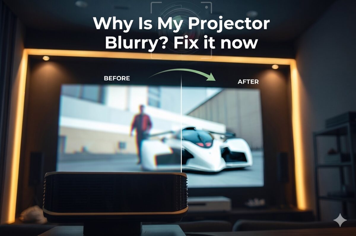
What Does "Blurry in Daylight" Really Mean?
Clarifying terminology prevents misdiagnosis and inappropriate solutions.
Optical Blur vs. Contrast-Induced Fuzziness
True optical blur:
Physical defocus of the lens system
Uniform across all lighting conditions
Affects image equally in darkness and daylight
Correctable through focus adjustment
Caused by: Incorrect focus, wrong throw distance, lens contamination
Appears as: Soft edges, loss of fine detail, visible regardless of brightness
Contrast-induced fuzziness (daylight "blur"):
Perceptual effect from reduced contrast
Only occurs in bright environments
Image sharp in darkness, appears "blurry" in light
Not correctable by focus adjustment
Caused by: Insufficient brightness, ambient light washout
Appears as: Washed-out image, indistinct edges, loss of depth
The critical distinction: If your projector produces a perfectly sharp image at night but appears "blurry" during the day, you're experiencing contrast degradation, not optical problems. Adjusting focus will not resolve this issue—brightness and ambient light control are required.
How Human Vision Perceives Sharpness
Visual perception of sharpness depends primarily on luminance contrast at edges, not absolute detail.
Perceptual sharpness factors:
Edge contrast (most important):
Human vision detects sharpness through brightness differences at transitions
High contrast (white on black): Appears very sharp even at moderate resolution
Low contrast (gray on gray): Appears fuzzy even at high resolution
Threshold: <20% contrast difference appears fuzzy regardless of resolution
Spatial frequency response:
Fine details require high contrast to be visible
Coarse details visible even with lower contrast
Ambient light preferentially degrades high spatial frequencies
Result: Loss of perceived detail and "blur" appearance
Adaptive perception:
Eyes adapt to ambient brightness (pupil dilation)
Bright environments: Pupils contract, reducing sensitivity to subtle contrast
Dark environments: Pupils dilate, increasing contrast sensitivity
Daylight viewing physiologically less sensitive to projection contrast
Technical measurement: Contrast ratio predicts perceived sharpness better than resolution specifications. A 2000:1 contrast 1080p image appears sharper than a 200:1 contrast 4K image in practical viewing.
Measuring Contrast Ratio in Real Environments
Contrast ratio dramatically differs between manufacturer specifications (dark room) and real-world conditions (ambient light).
Contrast ratio formula: Contrast Ratio = Peak White Brightness ÷ Black Level Brightness
Example calculations:
Dark room (ideal conditions):
Peak white: 300 nits (projector output)
Black level: 0.03 nits (projector native)
Contrast ratio: 10,000:1 (manufacturer spec)
Result: Excellent perceived sharpness
Room with ambient light (50 lux):
Peak white: 300 nits (projector) + 15 nits (ambient reflection) = 315 nits
Black level: 0.03 nits (projector) + 15 nits (ambient reflection) = 15.03 nits
Contrast ratio: 21:1 (catastrophic degradation)
Result: Severe perceived blur/fuzziness
Bright daylight (500 lux):
Peak white: 300 nits + 150 nits (ambient) = 450 nits
Black level: 0.03 nits + 150 nits (ambient) = 150.03 nits
Contrast ratio: 3:1 (essentially unwatchable)
Result: Image barely visible, extreme blur appearance
Key insight: Ambient light adds constant brightness to both peak whites and blacks, but disproportionately affects blacks, destroying contrast ratio.
Why Ambient Light Makes Projectors Look Blurry
Understanding the mechanism enables appropriate solutions.
The Physics of Ambient Light Washout
Light behavior on projection screens determines image quality in bright environments.
Projection in darkness:
Projector emits light toward screen
Screen reflects light toward viewers
Black areas receive minimal projector light
White areas receive maximum projector light
High contrast between black and white areas
Projection with ambient light:
Projector emits light toward screen
Ambient light sources (windows, ceiling lights) also illuminate screen
Screen reflects both projector and ambient light
Black areas now receive significant ambient light (appear gray)
White areas receive projector + ambient light (slightly brighter)
Low contrast between now-gray blacks and moderately bright whites
Ambient light sources:
Direct sunlight through windows (10,000-100,000+ lux)
Indirect daylight from north-facing windows (1,000-5,000 lux)
Overhead LED/fluorescent lighting (300-500 lux)
Task lighting and lamps (100-300 lux)
Light-colored walls reflecting light onto screen (50-200 lux)
Electronic displays (TVs, monitors, phones) in room (10-50 lux)
Critical understanding: Even moderate ambient light (300 lux) completely overwhelms typical projector black levels, transforming a 10,000:1 contrast ratio into 50:1 or worse.
Why Contrast Ratio Matters More Than Resolution
Resolution provides pixel detail; contrast ratio makes it visible.
Contrast ratio impact on perceived quality:
Contrast Ratio | Image Appearance | Perceived Sharpness | Suitable Use Cases |
10,000:1+ | Excellent blacks, vivid colors | Very sharp, all detail visible | Dark room cinema, professional |
3,000:1 | Good blacks, saturated colors | Sharp, most detail clear | Dim lighting, controlled ambient |
1,000:1 | Acceptable blacks, decent colors | Adequate sharpness | Moderate ambient light |
500:1 | Gray blacks, washed colors | Reduced sharpness | Bright ambient light (marginal) |
200:1 | Very gray blacks, pale colors | Poor sharpness, fuzzy appearance | Heavy ambient (barely usable) |
<100:1 | No black level, ghost-like | Extremely fuzzy, barely readable | Daylight (essentially unusable) |
Resolution comparison (same contrast): |
4K at 1000:1: Appears sharper than 8K at 200:1
Detail visibility requires minimum 500:1 contrast
Text readability requires minimum 200:1 contrast
Any visible image requires minimum 50:1 contrast
Professional standard: AV integrators specify minimum 500:1 on-screen contrast ratio for acceptable presentation quality in commercial environments.
Light Color Temperature and Perceived Clarity
Color temperature of ambient light affects color accuracy and perceived sharpness.
Ambient light color impacts:
Warm light (2700-3000K - incandescent, warm LED):
Orange/yellow cast on screen
Reduces blue visibility
Color shifting creates apparent softness
Less problematic than cool light (less luminance per watt)
Neutral/Cool white (4000-5000K - office lighting):
Balanced spectrum washing out all colors equally
Higher luminance per watt (worse for contrast)
Neutral color cast
Most common commercial lighting
Daylight (5500-6500K - windows):
Highest luminance (intensity)
Blue-rich spectrum
Completely overwhelms projector output
Worst-case scenario for projection
Color temperature mismatch between projector (typically 6500K) and ambient light creates color accuracy problems that compound the contrast-induced fuzziness, making images appear even less sharp.
Brightness Requirements for Daylight Projection
Projector brightness (measured in ANSI lumens) must overwhelm ambient light for acceptable quality.
Understanding Lumens and Their Limits
Lumen specifications require context for real-world performance.
ANSI lumens definition: The standardized measurement of projector light output under controlled conditions, averaged across multiple screen positions.
Real-world lumen considerations:
Brightness degradation factors:
Lamp aging: 20-30% brightness loss by 2,000 hours (lamp-based)
Eco mode: 20-40% reduction for quieter operation/longer life
Color accuracy mode: 15-30% reduction (cinema/movie modes)
Dust accumulation: 5-10% loss per 1,000 hours without cleaning
Screen efficiency: 0.8-2.5× multiplier based on screen gain
Effective lumens formula: Effective Lumens = Rated Lumens × 0.7 (aging) × 0.8 (mode) × 0.9 (dust) × Screen Gain
Example:
5,000 lumen projector after 1,000 hours, cinema mode, normal dust, 1.3 gain screen
Effective: 5,000 × 0.85 × 0.8 × 0.95 × 1.3 = 4,216 effective lumens
Laser projector advantage (June 2026 standard): 20,000+ hour lifespan with minimal degradation (5-10% over lifetime), maintaining brightness consistency.
Calculating Required Lumens for Daylight Use
Systematic calculation prevents under-specification and disappointing results.
Basic lumens requirement formula: Required Lumens = Screen Area (sq ft) × Ambient Light (foot-candles) × Screen Reflectivity Factor
Simplified formula for metric users: Required Lumens = Screen Width (m) × Screen Height (m) × Ambient Light (lux) × 0.15
Practical calculations by environment:
Conference room (moderate ambient, 300 lux):
100" diagonal 16:9 screen: 2.14m × 1.2m = 2.57 sq m
Required lumens: 2.57 × 300 × 0.15 = 116 lumens per sq m
Total required: 116 × 2.57 = ~3,000 lumens minimum
Classroom (bright fluorescent, 500 lux):
120" diagonal 16:9 screen: 2.57m × 1.44m = 3.7 sq m
Required lumens: 3.7 × 500 × 0.15 = 278 lumens per sq m
Total required: 278 × 3.7 = ~5,000 lumens minimum
Retail display (daylight windows, 1,000+ lux):
80" diagonal 16:9 screen: 1.71m × 0.96m = 1.64 sq m
Required lumens: 1.64 × 1,000 × 0.15 = 246 lumens per sq m
Total required: 246 × 1.64 = ~4,000 lumens minimum (smaller screen still needs high lumens)
Outdoor/daylight (5,000+ lux):
Professional projection requires 10,000-30,000 lumens
Typically needs multiple projectors or LED video wall instead
Rule of thumb (2026 professional standards):
Dark room (<50 lux): 20-30 lumens per square foot
Dim room (50-200 lux): 40-60 lumens per square foot
Office lighting (200-500 lux): 80-120 lumens per square foot
Bright commercial (500-1,000 lux): 150-250 lumens per square foot
Daylight (1,000+ lux): 300+ lumens per square foot (often impractical)
Screen Size vs. Brightness Trade-offs
Larger screens require proportionally more lumens to maintain image quality.
Brightness distribution:
Light spreads across screen area
Larger screen = same lumens distributed over more area
Result: Brightness per unit area (luminance) decreases
Screen size comparison (same projector, 3,000 lumens, 300 lux ambient):
Screen Size | Screen Area | Brightness/sq ft | Contrast Est. | Quality |
80" diag | 27 sq ft | 111 lumens/sq ft | ~400:1 | Good |
100" diag | 42 sq ft | 71 lumens/sq ft | ~250:1 | Acceptable |
120" diag | 61 sq ft | 49 lumens/sq ft | ~175:1 | Marginal |
150" diag | 95 sq ft | 32 lumens/sq ft | ~100:1 | Poor (fuzzy) |
Key insight: Doubling screen size requires quadrupling lumens to maintain same brightness. 80" to 160" (2× linear) requires 4× lumens (3,000 to 12,000 lumens). |
Professional recommendation: For daylight presentation rooms, specify smaller screens (80-100") with higher-lumen projectors (4,000-6,000 lumens) rather than large screens (120-150") with insufficient brightness.
Ambient Light Rejecting (ALR) Technology Explained
ALR screens provide the most cost-effective solution for daylight projection improvement.
How ALR Screens Work
ALR technology selectively reflects projected light while rejecting ambient light.
ALR screen types (June 2026):
Angular rejection (geometric):
Micro-structured surface with directional properties
Reflects light arriving from projector angle (typically ceiling mount)
Absorbs/redirects light arriving from other angles (ceiling lights, windows)
Examples: Screen Innovations Black Diamond, Elite Screens Aeon CLR
Lenticular design:
Fine vertical ridges on screen surface
Directs projector light toward viewing area
Rejects ambient light from above/below
Best for: Ultra-short-throw projectors, ceiling-mounted standard throw
Multi-layer optical:
Multiple layers with different optical properties
Filters specific angles and wavelengths
Most effective but expensive ($$$)
Examples: Stewart Filmscreen BalanceMAX, dnp Supernova
Wavelength-selective (rare, specialized):
Rejects specific wavelengths (fluorescent light spectra)
Passes laser or lamp spectra from projector
Limited applicability (requires spectrum matching)
Performance metrics:
ALR Type | Ambient Rejection | Gain | Viewing Angle | Cost Multiplier |
Standard white | None (1.0×) | 1.0 | 160° | 1× (baseline) |
Gray screen | 1.5-2× | 0.8-0.9 | 160° | 1.5× |
Basic ALR | 3-5× | 0.8-1.3 | 120-140° | 3-4× |
Premium ALR | 5-10× | 1.0-1.5 | 100-130° | 5-8× |
Real-world contrast improvement: Premium ALR screen can improve effective contrast from 50:1 to 300:1 in bright environments—the difference between "barely usable" and "acceptable presentation quality." |
ALR Screen Limitations and Trade-offs
ALR technology isn't a magic solution—understand limitations for realistic expectations.
Viewing angle reduction:
Optimal viewing within ±30-45° of center
Off-axis viewing shows brightness loss, color shift
Not suitable for wide rooms with broad seating
Best for: Narrow conference rooms, dedicated theater seats
Hot-spotting:
Brighter center area where projector angle optimal
Darker edges/corners from non-optimal angles
More pronounced with higher gain ALR screens
Requires careful projector positioning
Visible texture/structure:
Micro-structures visible at close distances
Recommended viewing distance: 1.5-2× screen width minimum
Fine detail may appear slightly softened
Trade-off: Ambient rejection vs. micro-texture visibility
Cost considerations (June 2026 typical pricing):
100" standard white screen: $300-800
100" basic ALR screen: $1,200-2,500
100" premium ALR screen: $2,500-6,000
Installation complexity: ALR screens more sensitive to positioning
When ALR makes sense:
Moderate to bright ambient light (300-1,000 lux)
Light control not feasible (architectural constraints)
Budget available for screen investment
Viewing geometry compatible (not too wide)
When ALR isn't sufficient:
Extreme daylight (direct sunlight, >2,000 lux)
Budget constraints (ALR costs more than brighter projector sometimes)
Very large screens (ALR can't overcome physics of insufficient lumens)
Architectural Light Control Solutions
Environmental modification often delivers better results than equipment upgrades.
Window Treatment Options
Controlling daylight provides maximum contrast improvement per dollar invested.
Window treatment effectiveness:
Blackout shades/curtains:
Light blocking: 99-100% (best option)
Cost: $100-500 per window
Operation: Manual or motorized
Aesthetics: Room-darkening (dedicated theaters)
Control: Complete when closed
Light-filtering shades:
Light blocking: 70-90%
Cost: $75-300 per window
Operation: Manual standard, motorized optional
Aesthetics: Maintains some ambient light
Control: Good for most presentation needs
Vertical blinds:
Light blocking: 60-80% (when closed/angled)
Cost: $50-200 per window
Operation: Manual typical
Aesthetics: Commercial appearance
Control: Moderate, some light leakage
Tinted window film:
Light blocking: 50-70%
Cost: $5-15 per sq ft installed
Operation: Permanent (no operation)
Aesthetics: Darker appearance always
Control: Constant reduction, not variable
Motorized shade benefits:
Integration with control systems (Crestron, Control4)
Automated operation (close when projector turns on)
Scene programming (presentation mode = close shades)
Cost premium: +$200-800 per shade for motorization
ROI: Justified in professional installations with frequent use
Implementation strategy:
Identify primary light sources (south/west windows worst)
Prioritize treatment of highest-impact windows first
Specify motorized for frequently adjusted windows
Manual acceptable for occasionally used rooms
Budget 15-25% of projector cost for window treatments in daylight rooms
Strategic Lighting Design
Artificial lighting design minimizes projector interference while maintaining room functionality.
Lighting zone control:
Separate circuits/zones:
Divide room into functional zones
Screen wall zone: Switched independently, turned off during projection
Seating area zone: Dimmable for note-taking during presentations
Entry/back zone: Pathway lighting, minimal impact on screen
Cost: $500-2,000 depending on electrical complexity
Dimming systems:
0-10V dimming: Commercial standard, smooth control
DALI: Advanced commercial, individual fixture addressing
Lutron/smart systems: Residential and commercial, scene programming
Integration: Tie to projector on/off (auto-dim when projecting)
Cost: $1,000-5,000 for typical conference room
Lighting fixture selection:
Avoid for projection rooms:
Recessed downlights aimed toward screen
Fluorescent troffer lights (high light output)
White/light-colored ceiling near screen (reflects onto screen)
Unshielded fixtures (light in all directions)
Prefer for projection rooms:
Indirect/uplight fixtures (light directed to ceiling, not screen)
Wall washers aimed away from screen wall
Task lighting at tables (focused downward)
Directional spots aimed away from screen
Low-output ambient during presentations
Wall color strategy:
Paint screen wall dark gray or black (absorbs stray light)
Ceiling near screen: Dark color (reduces light bounce)
Side walls: Neutral gray (better than white)
Back wall: Can remain lighter (minimal impact)
Presentation Scheduling and Usage Patterns
Operational adjustments can avoid daylight problems without equipment changes.
Time-of-day scheduling:
Schedule presentations for morning (east windows) or afternoon (west windows)
Avoid peak sunlight (10 AM - 2 PM for south-facing rooms)
Evening use ideal (natural darkness)
Cloudy days significantly better than sunny (50-70% light reduction)
Seasonal considerations:
Winter: Lower sun angle, more direct window light (worse for projection)
Summer: Higher sun angle, less direct penetration (better)
Fall/Spring: Variable, adjust as needed
Usage pattern optimization:
Critical presentations: Schedule during optimal times (early morning, late afternoon, evening)
Internal meetings: Accept reduced quality during mid-day if necessary
Training sessions: Multi-hour sessions can wait for evening start
Recorded content: Pre-record during optimal conditions, playback anytime
Technology Solutions for Daylight Projection
Equipment selection and configuration address brightness and contrast challenges.
High-Brightness Projector Selection (2026 Standards)
Projector technology has evolved significantly—understand current capabilities.
Projector categories by brightness (June 2026):
Consumer/home theater (1,000-3,000 lumens):
Target use: Dark dedicated theaters
Daylight capability: None
Cost: $800-3,000
Technology: Lamp or entry-level laser
Corporate/education (3,000-6,000 lumens):
Target use: Conference rooms, classrooms with light control
Daylight capability: Moderate ambient acceptable
Cost: $1,500-5,000
Technology: Lamp or mid-range laser
High-brightness installation (6,000-12,000 lumens):
Target use: Large venues, bright environments
Daylight capability: Good with ALR screen
Cost: $4,000-15,000
Technology: Laser phosphor or lamp
Professional venue (12,000+ lumens):
Target use: Auditoriums, stadiums, outdoor
Daylight capability: Excellent with proper screen
Cost: $15,000-150,000+
Technology: Laser RGB, xenon, LED
Laser projector advantages (2026 standard):
20,000-30,000 hour lifespan (vs. 2,000-5,000 for lamps)
Instant on/off (no warm-up/cool-down)
Consistent brightness (5-10% degradation over life vs. 30-50% for lamps)
Better color gamut (especially laser RGB)
Lower maintenance (no lamp replacement)
Cost premium: 30-50% more initially, ROI in 3-5 years
Brightness recommendations by application:
Application | Screen Size | Ambient Light | Minimum Lumens | Recommended |
Conference room | 80-100" | 300-500 lux | 3,500 | 4,500-6,000 |
Classroom | 100-120" | 400-600 lux | 5,000 | 6,000-8,000 |
Auditorium | 150-200" | 200-400 lux | 8,000 | 10,000-15,000 |
Retail display | 60-80" | 500-1,000 lux | 4,000 | 5,000-7,000 |
Trade show | 80-120" | 800-1,500 lux | 7,000 | 10,000-15,000 |
AI-Enhanced Brightness Management (2026 Technology)
Artificial intelligence in modern projectors automatically optimizes for ambient conditions.
AI adaptive brightness features:
Ambient light sensing:
Built-in light sensors measure room brightness continuously
Automatic adjustment of brightness output to match conditions
Dynamic iris control (if equipped) for contrast enhancement
Color gamut adjustment to maintain saturation in bright environments
Content-aware optimization:
Scene analysis determines content type (presentation, video, photos)
Brightness mapping optimizes per scene (brighter for graphics, natural for video)
Automatic HDR tone mapping (though largely ineffective in daylight)
Motion detection adjusts processing for sports vs. cinema
Smart mode selection:
AI picture modes automatically select optimal settings
Learning algorithms adapt to user preferences over time
Environmental profiles save settings per location/time-of-day
AI features in premium 2026 projectors:
Sony VPL series: "Ambient Adaptive" mode with predictive optimization
Epson Pro series: "Content Recognition AI" with scene-specific adjustment
JVC DLA series: "Theater Optimizer AI" with multi-sensor room analysis
Barco: "Pulse" processing with real-time ambient compensation
Effectiveness in daylight:
AI helps maximize available contrast given constraints
Cannot overcome fundamental physics of insufficient lumens
Best use: Fine-tuning already-adequate brightness systems
Not a substitute for sufficient lumens or light control
Multiple Projector and Projection Stacking
Combining projectors multiplies available brightness for extreme daylight applications.
Projection stacking (dual-projector overlay):
Two identical projectors project same image onto same screen area
Brightness additive: 5,000 + 5,000 = 10,000 lumens
Contrast improved: Black levels stay same, whites double
Alignment critical: Pixel-perfect registration required
Implementation requirements:
Identical projector models (same lens, same image processor)
Frame synchronization (genlock capability)
Precision mounting and alignment
Specialized processors for edge blending and color matching
Cost: 2× projector cost + processing equipment + installation
When stacking makes sense:
Extreme brightness needs (outdoor, bright retail, trade shows)
Large screens (200"+) in uncontrolled environments
Budget available ($20,000+ typical investment)
Professional installation with specialized expertise
Alternatives to stacking:
Single higher-brightness projector often more cost-effective
LED video wall if budget >$50,000 (better daylight performance)
Smaller screen with adequate single-projector brightness
Practical Solutions for Daylight Projection
Actionable strategies for improving daylight projection in existing installations.
Quick Improvements Without Equipment Changes
Immediate actions to improve daylight clarity with existing equipment.
Optimize projector settings:
Switch to brightest mode:
Select Dynamic, Bright, or Presentation picture mode
Disable Eco mode (increases brightness 20-40%)
Maximize brightness and contrast sliders
Accept reduced color accuracy for increased visibility
Disable unnecessary processing:
Turn off noise reduction (reduces light output)
Disable motion interpolation (processing overhead)
Turn off HDR for bright environments (SDR brighter)
Optimize lamp usage (lamp-based projectors):
Verify lamp hours (replace if >75% of rated life)
Clean air filters (improves cooling, allows higher brightness)
Reset lamp timer if lamp recently replaced
Environmental adjustments:
Close all window treatments completely
Turn off unnecessary lights (especially near screen)
Remove reflective objects from room (whiteboards, glass tables)
Darken screen wall with temporary coverings if possible
Schedule presentations for lower ambient light times
Screen positioning:
Raise screen higher on wall (away from window light sources)
Angle screen slightly downward (if possible) to reject ceiling light
Add side masking with black fabric/panels to increase perceived contrast
Medium-Term Upgrades (Months to Implement)
Significant improvements requiring budget allocation but not full system replacement.
Screen upgrade to ALR ($1,000-4,000):
Research ALR options compatible with projector mounting (UST vs. standard throw)
Verify viewing geometry (ALR works best with narrow viewing angles)
Budget 3-6× standard screen cost
Schedule installation during facility downtime
Expected improvement: 3-5× effective contrast in bright environments
Motorized window treatment ($500-2,000 per window):
Specify blackout or high-percentage light filtering
Integrate with control system (auto-close with projector on)
Focus on highest-impact windows (south/west facing)
Include override for manual operation when needed
Lighting zone upgrade ($1,000-5,000):
Add dimming circuits for lights near screen
Separate screen area lights on independent switch
Install occupancy sensors to turn off lights when room empty
Integrate with presentation system for one-touch operation
Smaller screen consideration (cost-effective):
80" screen appears much brighter than 120" screen (same projector)
Image quality may be acceptable at smaller size with existing lumens
Viewing distance may need adjustment (closer seating)
Cost: Screen replacement only ($300-800)
Long-Term Solutions (Major Investment)
Comprehensive solutions for permanent daylight projection capability.
High-brightness projector upgrade ($4,000-15,000):
6,000-12,000 lumen laser projector
Factor ongoing costs: Laser = low, lamp = ongoing replacement
Calculate ROI: Laser premium pays back in 3-5 years
Specify for room: Use calculator to determine required lumens
Professional installation: Critical for alignment and optimization
Architectural modifications ($5,000-30,000+):
Window replacement with tinted/UV-blocking glass
Interior shades built into window wells
Ceiling treatment (dark acoustic tiles near screen)
Wall color changes (dark screen wall)
Lighting system overhaul with zoning and control integration
Alternative display technology:
LED video wall (direct-view LED): $30,000-200,000+
Best daylight performance (emissive, not reflective)
No projector limitations (brightness, throw distance, focus)
Higher upfront cost, lower operating cost
Better for bright environments (>1,000 lux consistently)
Large-format LCD (98-110"): $8,000-25,000
Good brightness (500-700 nits typical)
Acceptable daylight performance for smaller spaces
Size-limited (110" maximum typically)
More affordable than LED wall
Decision matrix (when to choose each):
Stick with projection if:
Ambient light <500 lux with control options
Budget $5,000-15,000 available
Screen size >100" required
Installation complexity acceptable
Consider LED video wall if:
Ambient light >1,000 lux unavoidable
Budget >$50,000 available
Maximum brightness and daylight performance critical
Professional venue or permanent installation
Consider large LCD if:
Screen size <110" acceptable
Moderate brightness environment
Budget $10,000-25,000
Simpler installation preferred
Common Mistakes to Avoid
Preventing misdiagnosis and ineffective solutions saves time and money.
Trying to "Fix" Contrast Problems with Focus
The mistake: Repeatedly adjusting focus trying to sharpen daylight-washed image.
Why it fails: Focus addresses optical blur, not contrast degradation. No amount of focus adjustment will restore contrast lost to ambient light washout.
Correct diagnosis:
Test same content in darkness vs. daylight
If sharp in darkness: Brightness/contrast problem, not focus
If blurry in both: Focus problem, adjust accordingly
Assuming Higher Resolution Solves Daylight Blur
The mistake: Upgrading from 1080p to 4K expecting daylight performance improvement.
Why it fails: Resolution adds detail; brightness and contrast make it visible. A 4K projector at 200:1 contrast (daylight) looks worse than 1080p at 1000:1 (darkness).
Correct approach: Prioritize lumens and contrast over resolution for daylight applications. 4K is worthwhile only after brightness/contrast adequate.
Neglecting Screen Reflective Properties
The mistake: Focusing solely on projector brightness while using inappropriate screen.
Why it fails: Low-gain screens (0.8-1.0) reduce effective brightness. High-gain non-ALR creates hot-spotting without rejecting ambient.
Correct approach: Match screen to application:
Moderate ambient: Gray screen (0.9 gain) or basic ALR
Bright ambient: Premium ALR with 1.3+ gain and rejection
Dark room: Standard white (1.0 gain) for maximum color accuracy
Over-relying on Picture Settings Adjustments
The mistake: Spending hours tweaking brightness, contrast, sharpness settings trying to overcome insufficient lumens.
Why it fails: Picture settings can only redistribute existing light, not create more. Maxed-out settings create clipped whites and crushed blacks without solving fundamental brightness deficit.
Correct approach: Verify adequate lumens first using calculations. Settings optimization provides 5-10% improvement at most, not 500% needed for serious ambient light.
Frequently Asked Questions
Why does my projector look fine at night but blurry during the day?
Ambient light raises black levels, destroying contrast ratio from 5,000:1+ (night) to <200:1 (day). Your eyes perceive this contrast loss as blur even though optical focus is identical. The projector isn't actually blurry—it's contrast-deficient in daylight. Solutions: increase lumens, use ALR screen, or improve light control.
How many lumens do I need for a bright conference room?
Minimum 3,500 lumens for 100" screen in 300-500 lux ambient (typical overhead lighting). Recommended 5,000-6,000 lumens for comfort margin and future degradation. Use formula: Screen Area (sq meters) × Ambient Light (lux) × 0.15 = Required Lumens. Smaller screens need fewer lumens; larger screens need proportionally more.
Will an ALR screen eliminate the need for a brighter projector?
No. ALR screens improve effective contrast 3-10× but cannot create light. With insufficient base lumens, even ALR cannot produce acceptable image. ALR is multiplicative enhancement, not additive. Specify adequate lumens first, then add ALR for additional 3-5× improvement. Best results: 4,000+ lumen projector with premium ALR screen.
Is it better to get a brighter projector or an ALR screen?
Depends on ambient light level. Moderate ambient (300-500 lux): ALR screen delivers better value (3-4× contrast improvement for $1,000-2,500). Bright ambient (500-1,000+ lux): Need both—brighter projector (6,000+ lumens) plus ALR screen. Very bright (>1,000 lux): Consider alternatives (LED video wall) as even combined solution marginal.
Can I use HDR with daylight projection?
No, not effectively. HDR requires deep blacks and high peak brightness simultaneously. Daylight raises black levels to gray, eliminating HDR benefit. HDR in daylight produces dark, muddy image worse than SDR. Disable HDR for bright environments—SDR delivers better perceived quality when contrast ratio <500:1.
Why doesn't my 4K projector look sharper than my old 1080p in daylight?
Insufficient contrast prevents visibility of 4K detail. Contrast ratio determines perceived sharpness more than resolution. Your 4K projector (3,000 lumens) at 200:1 daylight contrast looks worse than 1080p (5,000 lumens) at 400:1 contrast. Solution: Increase brightness or reduce ambient light—then 4K advantage becomes visible.
Should I just buy the brightest projector available?
Not necessarily. Very high brightness (>10,000 lumens) projectors are expensive ($10,000-30,000+), generate more heat, create more noise, and may have reduced contrast in dark scenes. Specify appropriate brightness for your specific ambient conditions using calculations. Over-spec by 20-30% for headroom, not 200%. Often 6,000 lumen projector with ALR screen outperforms 10,000 lumen projector with standard screen.
Conclusion
Daylight projection blur is fundamentally a contrast degradation problem, not an optical focus issue, requiring brightness-based solutions rather than lens adjustments. Understanding that "projector picture problems" in bright environments stem from ambient light raising black levels and destroying contrast ratio enables AV professionals to specify appropriate equipment and environmental controls. The question "why is my projector blurry" during daylight has a clear answer: insufficient brightness relative to ambient light creates perceived fuzziness through contrast loss, even when the projector is perfectly focused.
The systematic approach detailed in this guide—calculating required lumens based on screen size and ambient light levels, implementing architectural light control, specifying ALR screens for moderate-to-bright environments, selecting appropriate projector brightness (typically 4,000-8,000 lumens for commercial spaces), and setting realistic expectations about daylight projection limits—enables practitioners to deliver functional projection systems in challenging lighting conditions that would otherwise produce unusable images.
In June 2026, laser projector technology, AI adaptive brightness, and advanced ALR screens have made daylight projection more viable than ever, but fundamental physics still governs performance: ambient light must be overwhelmed or rejected for acceptable image quality. The cost-benefit analysis often favors architectural light control (motorized shades, lighting zones) as the most effective per-dollar investment, with equipment upgrades (higher lumens, ALR screens) providing multiplicative improvements when combined with environmental optimization.
For AV integrators, system designers, and consultants, the critical skill is matching technology to application requirements. A 3,000-lumen projector in a light-controlled dedicated theater delivers reference-quality images, while a 10,000-lumen installation in an uncontrolled retail space with direct sunlight still produces marginal results. Success in daylight projection requires comprehensive solutions: adequate projector brightness, effective ambient light management, appropriate screen technology, and most importantly, realistic client expectations about what projection can and cannot achieve in bright environments. When ambient light exceeds 1,500-2,000 lux consistently, alternative display technologies (LED video walls, large-format LCDs) often provide better total-cost-of-ownership and user satisfaction than attempting to make projection work in fundamentally unsuitable conditions.
How to Create Professional AV Rack Layouts Using Rack Diagram Software
Creating professional AV rack layouts is a fundamental skill that separates successful AV system integrators from those struggling with installation delays, costly rework, and client dissatisfaction in 2026. The direct answer: professional rack diagram software transforms complex rack design from a tedious, error-prone manual process into a systematic, automated workflow that produces comprehensive documentation in a fraction of the time. Modern rack design software leverages intelligent automation, validation algorithms, and industry-specific knowledge to create rack layouts that optimize thermal performance, minimize installation errors, and communicate system architecture clearly to all project stakeholders.
The importance of choosing the best software for rack design cannot be understated. Your platform determines whether creating a complete rack elevation takes 30 minutes or 4 hours. It influences whether installation teams arrive with clear guidance or ambiguous instructions. It affects whether design changes require simple updates or complete redrawing. Professional rack diagram tools equipped with AV-specific features, automated layout generation, BOM synchronization, and comprehensive documentation capabilities enable integrators to deliver projects faster, more accurately, and more profitably.
Key Takeaways
Professional AV rack layouts require systematic planning of equipment placement, power distribution, thermal management, cable routing, and service access
Modern rack diagram software reduces design time by 70-85% through intelligent automation while improving accuracy and consistency
Essential rack layout components include equipment positioning, RU assignments, front/rear elevations, cable documentation, power calculations, and thermal analysis
A systematic design process follows: requirements gathering, equipment selection, automated layout generation, thermal optimization, cable planning, validation, and documentation creation
Best practices include using heat-aware placement, maintaining proper spacing, following cable management standards, planning for service access, and documenting comprehensively
Common mistakes include ignoring thermal management, inadequate spacing, poor cable organization, neglecting weight distribution, and incomplete documentation
XTEN-AV X-Draw leads the industry with AI-powered automation, heat-aware algorithms, BOM synchronization, and complete AV documentation capabilities
Professional rack layouts directly impact installation efficiency, system reliability, client satisfaction, and project profitability
Step-by-step workflows ensure consistent, error-free designs regardless of designer experience level
What Is an AV Rack Layout?
An AV rack layout is a detailed visual and technical representation showing exactly how audiovisual equipment will be organized within 19-inch standard racks or custom enclosures. These layouts serve as comprehensive blueprints that guide installation teams in building rack configurations correctly, efficiently, and safely.
Components of AV Rack Layouts
Professional rack layouts encompass multiple interconnected elements:
Equipment positioning: Exact placement of each device within rack units (RU)
Front elevation views: Visual representation showing device faceplates, indicators, and controls
Rear elevation views: Detailed mapping of connector locations, cable access points, and service panels
RU assignments: Precise specification of which rack units each device occupies
Power documentation: Circuit assignments, PDU connections, and power consumption calculations
Cable routing plans: Paths for signal cables, control wiring, and network connections
Thermal considerations: Heat load calculations and ventilation strategies
Weight distribution: Load analysis ensuring rack stability and floor capacity compliance
Service access planning: Clearances for equipment maintenance and future modifications
Types of AV Rack Layouts
Professional integrators create various rack documentation types depending on project phase and audience:
Preliminary layouts: Early-stage designs for client approval and budget estimation
Engineering layouts: Detailed technical drawings for internal design teams
Installation layouts: Comprehensive guides with all information field teams need
As-built documentation: Final records reflecting actual completed installations
Maintenance layouts: Reference materials for service technicians and facility managers
Why Professional Rack Layouts Matter in AV Projects
The quality of rack layouts directly impacts every subsequent project phase, from equipment procurement through long-term service.
Installation Efficiency and Accuracy
Detailed professional layouts enable installation teams to work quickly and confidently. When technicians arrive on-site with comprehensive rack elevations, clear RU assignments, complete cable schedules, and accurate equipment specifications, they execute installations with minimal confusion or delays.
Research across the AV integration industry shows that projects using professional rack layouts experience:
45-60% faster installation times
65-85% fewer mounting errors
70-80% reduction in cable misconnections
85-95% improvement in first-time commissioning success
Reduced Rework and Cost Overruns
Installation errors stemming from inadequate rack documentation typically cost 15-25% of project budgets in rework expenses, schedule delays, and opportunity costs. Professional layouts prevent these problems by providing complete, accurate information that eliminates ambiguity and prevents mistakes.
Enhanced Client Communication
High-quality rack diagrams communicate system design far more effectively than equipment lists or verbal descriptions. Clients understand how their systems will be organized, what equipment will be installed, and how racks will appear in their facilities. This visual clarity facilitates faster approvals and builds confidence in integrator competence.
Improved System Reliability
Professional layouts incorporate thermal management, proper spacing, and strategic equipment positioning that enhance system reliability. Racks designed with attention to airflow, heat distribution, and service access experience fewer equipment failures and require less maintenance over their operational lifetimes.
Compliance and Standards Adherence
Many AV projects must meet specific building codes, fire safety regulations, accessibility standards, or client specifications regarding equipment organization, power distribution, and cable management. Professional layouts demonstrate compliance systematically through detailed documentation.
Long-Term Service Value
Years after initial installation, accurate rack layouts become invaluable when service technicians troubleshoot problems, replace failed components, or implement system upgrades. As-built documentation showing exact equipment locations, signal paths, power connections, and network assignments dramatically reduces service time and costs.
Common Challenges When Designing AV Rack Layouts
AV integrators face numerous obstacles when creating rack layouts using traditional methods or inadequate tools.
Time-Intensive Manual Processes
Creating detailed rack elevations manually requires painstaking placement of individual devices, precise RU calculations, manual measurement verification, and constant reference to equipment specifications. A single comprehensive rack layout can consume 4-8 hours of designer time using basic CAD tools or drawing software.
Thermal Management Complexity
Calculating cumulative heat loads, predicting airflow patterns, identifying potential hot spots, and optimizing equipment positioning for proper thermal performance requires specialized knowledge and significant analysis. Without dedicated thermal management tools, designers often overlook these critical considerations.
Cable Documentation Burden
Documenting every signal connection, power cable, and control wire with proper labeling, routing information, and termination specifications represents one of the most tedious aspects of rack design. Manual cable documentation is extremely time-consuming and highly prone to errors.
Equipment Specification Accuracy
Ensuring device dimensions, power requirements, mounting specifications, and connector locations are accurate requires constant reference to manufacturer datasheets. Manual data entry introduces numerous opportunities for errors that lead to field problems.
Design Change Management
AV projects frequently experience equipment substitutions, scope modifications, or budget adjustments during design and procurement phases. Updating manually created rack layouts to reflect these changes requires substantial rework, often necessitating complete redrawing.
Version Control and Collaboration
When multiple team members work on projects using file-based tools, maintaining current documentation versions becomes challenging. Designers, project managers, and installation supervisors may work from different layout versions, creating confusion and errors.
Standards and Consistency
Without standardized tools and templates, rack layout quality varies significantly between designers and projects. Inconsistent documentation formats, varying detail levels, and non-standard conventions confuse installation teams and reduce professional credibility.
What Is Rack Diagram Software?
Rack diagram software is a specialized digital platform purpose-built to streamline the creation of professional rack layouts for AV systems, data centers, broadcast facilities, and other equipment-intensive installations. These platforms transcend basic drawing capabilities, incorporating industry-specific intelligence, automation algorithms, and workflow integration that transform rack design from manual labor into systematic, error-resistant processes.
Core Capabilities
Professional rack design platforms deliver comprehensive functionality including:
Intelligent equipment libraries containing thousands of manufacturer-specific devices with accurate specifications
Automated layout generation creating optimized rack configurations based on equipment selections
Real-time validation checking for space conflicts, power issues, thermal problems, and compatibility errors
Visual design interfaces with drag-and-drop equipment placement
Front and rear elevation generation showing complete rack views
Thermal analysis tools calculating heat loads and recommending placement strategies
Cable management systems for planning routing, generating labels, and creating schedules
Power distribution planning with circuit assignments and load calculations
BOM integration synchronizing equipment lists with rack layouts
Documentation automation generating complete technical packages
Collaboration features enabling distributed teams to work together
Multi-format export supporting PDF, CAD, Visio, and other industry formats
Evolution and Modern Features
Contemporary rack diagram software has evolved significantly from early drawing tools. Today's platforms incorporate:
AI-powered automation reducing manual design work by 70-85%
Cloud-based architecture enabling access from anywhere
Mobile responsiveness for field team access
Heat-aware algorithms optimizing thermal performance
Predictive validation identifying potential problems before installation
Workflow integration connecting with proposal, project management, and procurement systems
How Rack Diagram Software Simplifies AV Rack Design
Professional rack design platforms address the core challenges integrators face, transforming rack layout creation from burden to competitive advantage.
Automated Layout Generation Eliminating Manual Placement
Modern software automatically generates optimized rack configurations based on selected equipment. Instead of manually positioning every device and calculating RU assignments, designers simply specify required components, and intelligent algorithms create professional layouts in minutes.
This automation applies industry best practices for device ordering, thermal management, service access, and cable routing automatically, producing results superior to most manual efforts.
Real-Time Validation Preventing Errors
Software platforms continuously validate designs, alerting designers to problems immediately:
RU conflicts where equipment overlaps
Power capacity violations exceeding PDU ratings
Weight limits threatening rack stability
Depth clearances where devices exceed available space
Thermal issues from heat-generating equipment clustering
Compatibility problems between connected devices
Catching these errors during design prevents expensive field corrections.
Comprehensive Documentation from Single Source
Professional platforms generate complete documentation packages including rack elevations, cable schedules, power diagrams, signal flow charts, equipment specifications, and installation notes from unified data. This eliminates the need to create each document type separately in different tools, saving enormous time while ensuring consistency.
BOM Synchronization Maintaining Accuracy
Bidirectional integration between equipment lists and rack layouts ensures documentation remains current throughout project lifecycles. When equipment changes occur during procurement, layouts update automatically, preventing field teams from discovering documentation doesn't match actual equipment.
Thermal Management Tools Ensuring Reliability
Heat-aware placement algorithms analyze thermal characteristics and position devices to promote proper airflow. Visual heat mapping shows temperature distribution before installation, enabling proactive optimization that prevents equipment failures from inadequate cooling.
Cable Management Automation Saving Hours
Automated cable labeling generates consistent naming schemes, complete connection schedules, routing recommendations, and termination lists automatically. This eliminates one of the most time-consuming and error-prone aspects of rack documentation.
Cloud Collaboration Enabling Distributed Teams
Cloud-based platforms allow designers, project managers, sales teams, and installation supervisors to access and contribute to rack layouts simultaneously from any location. Everyone works from current information, eliminating version control confusion.
Essential Components of a Professional AV Rack Layout
Comprehensive professional layouts include multiple interconnected elements that together provide complete guidance for installation and service.
1. Detailed Equipment Positioning
Every device must be precisely located within the rack with exact RU assignments:
Starting RU position from rack bottom
RU height occupied by each device
Equipment identification with manufacturer and model number
Device orientation (front-mounted, rear-mounted, or internal)
Mounting method (rails, shelves, brackets)
2. Front Elevation Diagrams
Front views show what installation teams and end users see when facing racks:
Device faceplates with accurate proportions
Control panels, displays, and indicator lights
Access doors and security features
Ventilation panels and blanking plates
Labeling and identification
Aesthetic organization for client-facing installations
3. Rear Elevation Diagrams
Rear views detail connectivity and service access:
Connector panels showing exact port locations
Power inlets and circuit connections
Cable entry points and routing paths
Removable panels and service access points
Heat exhaust areas
Device depth relative to rack rails
4. Power Distribution Documentation
Complete electrical planning ensures safe, reliable operation:
PDU locations and mounting positions
Circuit assignments for each device
Power consumption calculations per circuit
Total load per PDU and rack
Voltage requirements (120V, 208V, 240V)
Plug types and connector specifications
Power sequencing requirements
UPS connections for critical equipment
5. Cable Management Plans
Comprehensive cable documentation guides accurate installation:
Cable types (analog audio, digital video, HDMI, fiber, Cat6, control)
Source and destination for every connection
Cable labels following consistent conventions
Routing paths through cable management
Cable lengths accounting for actual routing
Connector types at each end
Color coding schemes
Separation requirements for signal types
6. Thermal Management Information
Cooling considerations ensure reliable long-term operation:
Heat load calculations for each device
Cumulative heat generation per rack
Airflow direction requirements
Blanking panel placements filling empty spaces
Fan positions and specifications
Spacing requirements around high-heat devices
Ambient temperature assumptions
7. Weight Distribution Analysis
Load calculations prevent structural problems:
Individual device weights
Cumulative rack weight
Weight distribution (top-heavy vs. bottom-heavy)
Floor load capacity verification
Seismic considerations for appropriate regions
Stabilization requirements
8. Service Access Planning
Maintenance considerations facilitate future work:
Clearances for device removal
Cable service loops for equipment replacement
Access panels for internal devices
Front access vs. rear access requirements
Sliding rails or hinged brackets for deep devices
Step-by-Step Guide to Creating Professional AV Rack Layouts
A systematic design process ensures consistent, high-quality results regardless of project complexity.
Step 1: Gather Project Requirements and Specifications
Begin with comprehensive understanding of project needs:
Review functional requirements from client specifications
Identify all equipment needed for the AV system
Determine rack quantities, sizes, and types required
Understand site conditions including power availability, cooling capacity, and space constraints
Identify industry standards, building codes, or client preferences that must be followed
Clarify service access requirements and maintenance expectations
Establish timeline and budget parameters
Step 2: Select Equipment and Create Bill of Materials
Specify all devices that will populate racks:
Choose appropriate equipment meeting performance requirements
Verify device specifications including dimensions, power consumption, thermal output, and mounting requirements
Create detailed BOM with manufacturer, model numbers, quantities, and RU heights
Confirm equipment availability and lead times
Validate selections against budget constraints
Document any alternatives or substitution options
Step 3: Launch Rack Design Software and Create Project
Initialize your design platform:
Open rack diagram software (XTEN-AV X-Draw recommended)
Create new project with appropriate name and identifier
Enter project details, client information, and site data
Import BOM if software supports direct import
Set up rack configurations (quantity, height, width, depth)
Configure project preferences including labeling conventions, documentation formats, and company standards
Step 4: Add Equipment to Rack Using Automated Generation
Leverage software automation for initial layout:
Select equipment from software library or imported BOM
Use automated layout generation feature to create initial configuration
Review software recommendations for device positioning
Let algorithms apply best practices for thermal management and logical ordering
Accept automated layout as foundation for refinement
Step 5: Optimize Equipment Placement for Thermal Performance
Refine layout considering heat management:
Review thermal analysis and heat mapping provided by software
Verify heat-generating devices (amplifiers, processors) have adequate spacing
Position high-heat equipment with clear airflow paths
Place heat-sensitive devices away from hot zones
Add blanking panels in empty spaces to direct airflow
Consider fan placements if required
Ensure heat exhaust areas aren't blocked
Validate cumulative heat load against rack cooling capacity
Step 6: Plan Power Distribution and Circuit Assignments
Organize electrical requirements:
Position PDUs appropriately within racks
Assign each device to specific PDU outlets
Calculate circuit loads ensuring none exceed capacity
Distribute load evenly across available circuits
Plan power sequencing if required
Document UPS connections for critical equipment
Verify total power consumption against available capacity
Specify plug types and cord lengths
Step 7: Document Cable Connections and Routing
Create comprehensive cable documentation:
Use automated cable labeling features
Generate cable schedules showing all connections
Plan cable routing through rack cable management
Specify cable types, lengths, and connectors
Establish consistent labeling conventions
Separate power cables from signal cables appropriately
Document fiber optic vs. copper connections
Create service loops for future equipment replacement
Step 8: Validate Design Against Requirements
Perform thorough design review:
Run software validation tools checking for errors
Verify all functional requirements are met
Confirm equipment fits within rack dimensions
Validate power calculations are within capacity
Review thermal analysis for potential issues
Check weight distribution and rack stability
Ensure adequate service access and clearances
Verify compliance with standards and client specifications
Step 9: Generate Complete Documentation Package
Create comprehensive project deliverables:
Generate front and rear rack elevations
Create cable schedules and connection matrices
Produce power distribution diagrams
Export equipment specifications and cut sheets
Generate signal flow diagrams if required
Create installation notes and special instructions
Format documents per client requirements
Export to appropriate formats (PDF, CAD, Visio)
Step 10: Conduct Pre-Installation Review
Validate design before field work:
Review rack layouts with installation supervisors
Discuss potential field challenges or site constraints
Clarify any ambiguous aspects of documentation
Verify equipment has arrived and matches specifications
Confirm mounting hardware and accessories are available
Address any questions from installation team
Make final adjustments based on feedback
Distribute final documentation to all stakeholders
Best Practices for Professional AV Rack Design
Following industry best practices ensures rack layouts are functional, reliable, and maintainable.
Thermal Management Best Practices
Proper heat management is critical for system reliability:
Position high-heat devices (amplifiers, processors) with 1-2 RU spacing
Place heat-generating equipment in lower two-thirds of rack where cooling is more effective
Avoid clustering multiple hot devices together
Use blanking panels to direct airflow through equipment
Ensure rack has adequate ventilation (passive or active)
Consider hot-aisle/cold-aisle arrangements in multi-rack installations
Leave top RUs for cable management rather than heat-generating equipment
Plan for ambient temperature increases in enclosed spaces
Equipment Organization and Spacing
Logical device arrangement improves functionality and serviceability:
Group related equipment by function (signal processing, amplification, distribution)
Position frequently accessed devices at convenient heights (waist to shoulder level)
Place heavy equipment (UPS, amplifiers) in lower sections for stability
Maintain at least 1 RU spacing around devices requiring service access
Position devices with front controls where operators can reach them
Avoid mounting equipment directly at eye level where status LEDs create glare
Leave expansion space for future equipment additions
Cable Management Excellence
Professional cable organization improves installation quality and future serviceability:
Use vertical cable managers on rack sides for backbone cabling
Employ horizontal cable managers between groups of devices
Route cables away from heat exhaust areas
Maintain proper bend radius for all cable types
Separate power cables from signal cables to prevent interference
Keep audio cables away from video cables when possible
Use Velcro wraps instead of zip ties for easier cable modifications
Leave service loops at each device for future equipment replacement
Label both ends of every cable clearly
Color-code cables by type or function for easy identification
Power Distribution Planning
Reliable electrical design prevents problems and facilitates troubleshooting:
Size PDUs with 20-30% capacity headroom beyond calculated loads
Use switched/controlled PDUs when remote power management is needed
Distribute load evenly across available circuits
Place PDUs where power cords reach all devices without excessive length
Document circuit assignments clearly for future reference
Use locking power connectors for critical equipment
Plan power sequencing preventing inrush current issues
Include UPS for essential devices requiring backup power
Documentation Standards
Comprehensive, clear documentation is essential for installation success:
Use consistent labeling conventions across all projects
Include scale or dimensions on all drawings
Provide multiple views (front, rear, side) when helpful
Create legends explaining symbols, abbreviations, and color codes
Include revision dates and version numbers
Specify authors or designers responsible
Add notes for special installation requirements
Format documents professionally with company branding
Service Access Considerations
Plan for long-term maintenance and future modifications:
Ensure adequate clearance for device removal (typically 24-36 inches in front and rear)
Use sliding rails or hinged brackets for deep equipment
Position devices requiring frequent service at accessible heights
Avoid mounting equipment in ways that require other device removal for access
Include cable service loops allowing equipment replacement without re-termination
Document service procedures for complex configurations
Consider spare RU space for future expansion
Common AV Rack Layout Mistakes to Avoid
Learning from common errors helps designers create better rack configurations faster.
Mistake 1: Ignoring Thermal Management
Symptom: Clustering heat-generating equipment without adequate spacing or ventilation.
Consequences: Equipment overheating, premature failures, performance degradation, increased maintenance costs, and service callbacks.
Solution: Use heat-aware design tools, position hot devices with proper spacing, employ blanking panels, ensure adequate ventilation, and validate thermal performance during design.
Mistake 2: Inadequate Equipment Spacing
Symptom: Mounting devices with no gaps between them to maximize rack space utilization.
Consequences: Difficulty accessing devices for service, cable congestion, thermal issues, challenging equipment replacement, and installation delays.
Solution: Maintain 1 RU spacing around devices requiring regular access or generating significant heat. Accept that some rack space dedicated to service access improves long-term maintainability.
Mistake 3: Poor Cable Management Planning
Symptom: Failing to designate space for cable management or plan cable routing systematically.
Consequences: Cable congestion blocking airflow, difficult troubleshooting, challenging modifications, unprofessional appearance, and increased installation time.
Solution: Dedicate appropriate space to vertical and horizontal cable management, plan routing paths during design, and document cable organization clearly for installation teams.
Mistake 4: Neglecting Weight Distribution
Symptom: Concentrating heavy equipment in upper rack sections without considering stability.
Consequences: Rack instability, tipping hazards, structural stress, floor loading issues, and safety problems.
Solution: Position heavy devices in lower rack sections, calculate total weight and distribution, verify floor capacity, and consider seismic requirements for appropriate regions.
Mistake 5: Incomplete Cable Documentation
Symptom: Creating rack elevations without comprehensive cable schedules, labeling schemes, or connection details.
Consequences: Installation errors, miswiring, extended installation times, troubleshooting difficulties, and commissioning delays.
Solution: Use automated cable documentation features, create complete connection matrices, establish consistent labeling conventions, and include all cable specifications in documentation packages.
Mistake 6: Overlooking Service Access
Symptom: Designing racks where equipment can only be accessed by removing other devices.
Consequences: Complicated maintenance procedures, extended service times, unnecessary system downtime, and frustrated technicians.
Solution: Plan for adequate front and rear access, use appropriate mounting systems for deep equipment, position frequently serviced devices accessibly, and test access scenarios during design.
Mistake 7: Inconsistent Documentation
Symptom: Creating rack layouts with different formats, detail levels, or conventions across projects.
Consequences: Installation team confusion, increased error rates, longer learning curves, and reduced professional credibility.
Solution: Establish and enforce company-wide standards for rack documentation, use software templates encoding best practices, and train team members on consistent approaches.
Mistake 8: Ignoring BOM Synchronization
Symptom: Creating rack layouts separately from equipment lists without ongoing synchronization.
Consequences: Documentation showing wrong equipment, field teams discovering devices don't match drawings, procurement errors, and installation delays.
Solution: Use rack design software with BOM integration, ensure changes in equipment specifications update layouts automatically, and validate documentation matches actual equipment before installation.
How XTEN-AV X-Draw Helps Create Professional AV Rack Layouts
XTEN-AV X-Draw represents the most comprehensive rack design platform purpose-built for professional AV integrators, delivering capabilities specifically engineered to streamline professional rack layout creation.
Purpose-Built for AV Professionals
Unlike generic CAD tools or IT-focused rack planners, X-Draw was developed specifically for audiovisual system design. The platform inherently understands AV devices, signal routing, thermal requirements, and documentation standards without requiring extensive customization.
This AV-native approach means integrators achieve productive work immediately rather than spending weeks adapting general-purpose tools to AV workflows.
1. Automated Rack Layout Generation for Rapid Design
X-Draw automatically generates optimized rack layouts based on equipment selected for projects. Instead of manually positioning every device and calculating RU assignments, designers specify required components, and intelligent algorithms create professional configurations in minutes.
This automation applies industry best practices for device ordering, thermal management, service access, and cable routing, consistently producing results superior to most manual designs while reducing design time by 70-85%.
2. Heat-Aware Equipment Placement Ensuring Reliability
The platform employs sophisticated heat-adjustment algorithms that analyze thermal characteristics of each component and position devices promoting optimal airflow while minimizing overheating risks. X-Draw calculates cumulative heat loads, identifies potential hot spots, and recommends placement strategies ensuring reliable long-term operation.
This proactive thermal management prevents equipment failures that often don't manifest until after commissioning, saving costly service callbacks and client dissatisfaction.
3. Native AV-Specific Design Environment
X-Draw provides a purpose-built environment understanding AV devices, signal paths, rack structures, and documentation requirements without extensive configuration. This eliminates the learning curve and adaptation time associated with repurposing general tools for audiovisual applications.
4. Automatic Rack Elevation Creation
Once equipment is added to projects, X-Draw automatically generates professional rack elevation diagrams including front and rear views, complete device information, accurate RU assignments, and professional formatting meeting industry standards.
Designers create installation-ready documentation in minutes rather than the hours required for manual drawing.
5. Integrated BOM Synchronization Maintaining Accuracy
Changes made in Bills of Materials are automatically synchronized with drawings, ensuring rack layouts remain accurate throughout project lifecycles. X-Draw effectively transforms BOM data into technical drawings, eliminating manual updates that frequently introduce version control errors.
This synchronization prevents installation teams from discovering documentation doesn't match actual equipment delivered to sites.
6. Automatic Cable Labeling Eliminating Errors
Cable labeling represents one of the most time-consuming aspects of rack documentation. X-Draw automates this completely, generating consistent labeling schemes, complete cable schedules, connection matrices, and termination lists automatically based on equipment connectivity.
This automation saves hours per project while virtually eliminating miswiring errors during installation.
7. Complete AV Documentation Automation
Beyond rack diagrams, X-Draw generates comprehensive documentation packages including:
Signal flow diagrams showing complete system architecture
Line schematics detailing signal processing
Floor plans with equipment locations
Rack elevations (front and rear views)
Cable schedules with complete connection data
Integrators create entire project documentation from single sources, eliminating the need to juggle multiple specialized tools.
8. Extensive AV Product Library
The platform includes access to massive AV equipment databases with thousands of products from major manufacturers. Each device includes accurate dimensions, specifications, connector information, and thermal ratings ensuring designs reflect reality.
When products aren't available, users create custom devices seamlessly.
9. Cloud-Based Collaboration
Because X-Draw operates in the cloud, team members collaborate on projects from anywhere. Designers, sales teams, project managers, and installers work from single sources of truth, eliminating version confusion and communication gaps.
10. Multiple Export Formats Supporting Any Workflow
Rack diagrams and related documentation export to PDF, PNG, SVG, AutoCAD, Visio, HTML, and XML formats, ensuring compatibility with any client, consultant, or internal workflow.
11. Custom Device Creation
When products aren't available in standard libraries, users create custom devices and incorporate them into rack designs without disrupting workflows.
12. Built-In Proposal and Project Workflow Integration
Unlike standalone rack drawing tools, X-Draw is part of the broader XTEN-AV ecosystem, connecting rack diagrams with proposals, project documentation, product databases, and project management workflows.
13. Faster Design Revisions
AV projects frequently change during design and procurement. X-Draw enables rapid updates to rack layouts, signal flows, and documentation without redrawing entire systems from scratch.
14. AI-Powered AV Workflow Automation
XTEN-AV combines cloud technology and AI-driven automation to reduce repetitive design tasks, helping integrators complete projects faster while maintaining accuracy.

Why AV Integrators Choose X-Draw
The biggest advantage of X-Draw is that it eliminates the need to switch between multiple tools such as AutoCAD, Visio, rack planning software, documentation software, and proposal platforms. Professional AV integrators can design, document, collaborate, and generate project deliverables from single cloud-based platforms.
Frequently Asked Questions
What is the fastest way to create professional AV rack layouts?
The fastest method is using professional rack diagram software with automated layout generation like XTEN-AV X-Draw. Specify required equipment, and intelligent algorithms create optimized rack configurations in minutes applying best practices for thermal management, device ordering, and service access. This approach reduces design time by 70-85% compared to manual methods using CAD tools. The key is leveraging automation while maintaining ability to refine layouts for project-specific requirements. Software also automates cable documentation, power calculations, and elevation generation, creating complete documentation packages that would take hours manually.
How do I ensure proper thermal management in rack layouts?
Proper thermal management requires: positioning heat-generating devices (amplifiers, processors) with 1-2 RU spacing; placing hot equipment in lower two-thirds of racks where cooling is more effective; avoiding clustering multiple high-heat devices together; using blanking panels to direct airflow; ensuring adequate ventilation (passive or active); and calculating cumulative heat loads. Modern rack design software like X-Draw includes heat-aware algorithms that analyze thermal characteristics and recommend optimal placement automatically. Visual heat mapping shows temperature distribution before installation, enabling proactive optimization. This prevents equipment failures from inadequate cooling that often don't manifest until after commissioning.
What should be included in professional rack layout documentation?
Comprehensive rack documentation includes: front elevation diagrams showing device faceplates and controls; rear elevation diagrams displaying connector locations and cable access; exact RU assignments for each device; complete cable schedules with source, destination, cable type, and length; power distribution diagrams showing circuit assignments and load calculations; equipment specifications with manufacturer and model information; thermal analysis and heat load calculations; weight distribution data; installation notes for special requirements; and labeling conventions. Professional rack design software generates these components automatically from unified data sources, ensuring consistency and completeness while saving enormous time.
How do I handle design changes in rack layouts efficiently?
Efficient change management requires tools with BOM synchronization and parametric design capabilities. When equipment changes occur, platforms like X-Draw automatically update rack layouts, cable schedules, power calculations, and all related documentation without manual redrawing. This eliminates the hours typically spent revising designs manually. Cloud-based platforms also enable real-time collaboration where team members see changes immediately, preventing version control confusion. Establish change control processes where design revisions are reviewed before distribution, and maintain change logs documenting modifications. Automated tools enable rapid adaptation to equipment substitutions, scope changes, or specification revisions that frequently occur during AV projects.
What are the most common mistakes when creating rack layouts?
The most frequent errors include: ignoring thermal management by clustering heat-generating equipment without adequate spacing; inadequate spacing between devices impeding service access; poor cable management planning causing congestion and airflow blockage; neglecting weight distribution creating stability issues; incomplete cable documentation leading to installation errors; overlooking service access requirements; inconsistent documentation formats confusing installers; and failing to synchronize BOMs with layouts. Using professional rack diagram software with built-in validation and best practice templates prevents these mistakes automatically. Real-time error checking alerts designers to problems during design rather than discovering them during expensive installation phases.
Can I create professional rack layouts without expensive software?
While basic rack layouts can be created using free or inexpensive tools like Visio, PowerPoint, or online rack planning websites, these approaches lack automation, validation, thermal analysis, BOM integration, and documentation capabilities that professional software provides. The resulting designs take significantly longer to create, contain more errors, and produce inferior documentation. For professional AV integrators, the time savings and error reduction from specialized rack design software typically deliver ROI within 2-4 projects. Free tools may suffice for very simple installations or firms doing minimal rack design, but growing businesses quickly find that professional platforms pay for themselves through increased productivity and reduced rework costs.
How do I choose the right rack design software for my AV integration firm?
Evaluate platforms based on: AV-specific features and equipment libraries; automation capabilities for layout generation and documentation; BOM integration maintaining accuracy; thermal management tools; cable labeling automation; cloud-based collaboration; multi-format export; workflow integration with other systems; ease of use and learning curve; vendor support and training resources; pricing model and total cost of ownership; and scalability for firm growth. For most professional integrators, XTEN-AV X-Draw offers the most comprehensive capabilities specifically designed for AV workflows. Request demonstrations and trial periods to evaluate how software fits your specific needs before committing to subscriptions.
Conclusion
Creating professional AV rack layouts represents a fundamental skill that directly impacts project success, installation efficiency, system reliability, and client satisfaction. The systematic design process outlined in this guide—from requirements gathering through equipment selection, automated layout generation, thermal optimization, cable planning, validation, and documentation creation—ensures consistent, high-quality results regardless of project complexity or designer experience.
Modern rack diagram software, particularly XTEN-AV X-Draw, transforms this traditionally time-intensive manual process into an efficient, automation-driven workflow that reduces design time by 70-85% while improving accuracy and consistency. The intelligent algorithms, heat-aware placement, BOM synchronization, automated cable documentation, and comprehensive documentation generation capabilities these platforms offer eliminate the tedious manual work and error-prone calculations that plague traditional design methods.
Best practices including heat-aware device positioning, logical equipment organization, professional cable management, reliable power distribution, comprehensive documentation standards, and thoughtful service access planning separate professional integrators from competitors using improvised methods. Avoiding common mistakes like ignoring thermal management, inadequate spacing, poor cable planning, and incomplete documentation prevents the installation errors and rework that erode project profitability.
The step-by-step workflow presented provides a proven framework that AV integrators can implement immediately, whether creating their first rack layout or refining existing processes. Combined with professional rack design software, this systematic approach enables designers to produce installation-ready documentation that guides field teams to execute rack builds accurately, efficiently, and confidently.
For AV system integrators committed to delivering projects faster, more accurately, and more profitably while building scalable businesses capable of sustained growth, mastering professional rack layout creation using modern rack diagram software represents one of the highest-value skills to develop. The investment in learning systematic design processes and implementing proper tools delivers returns that compound across every subsequent project, positioning firms for long-term success in an increasingly competitive industry.
AV Wiring Diagram Software vs Traditional CAD Tools: Which Should You Choose?
The audiovisual integration industry stands at a critical crossroads in June 2026, where designers must choose between continuing with traditional CAD platforms that have dominated technical documentation for decades or transitioning to purpose-built AV wiring diagram software engineered specifically for audiovisual workflows. While many AV designers initially search for free wiring diagram software to minimize costs, the hidden expenses of inefficient workflows, extended project timelines, and increased error rates often make generic free tools far more expensive than specialized paid platforms in terms of total project costs and lost opportunities.
Choosing the best free wiring diagram software versus investing in specialized AV-specific platforms requires understanding the fundamental architectural differences between general-purpose CAD tools and intelligent automation systems purpose-built for audiovisual integration. Traditional CAD software like AutoCAD, DraftSight, or LibreCAD treats AV equipment as generic rectangles requiring extensive manual customization, while specialized platforms like XTEN-AV's X-DRAW incorporate manufacturer databases, signal flow intelligence, automated rack generation, and BOM integration that transform documentation workflows from labor-intensive drafting to streamlined design automation. This comparison examines both approaches to help AV integrators make informed platform decisions that maximize efficiency, profitability, and competitive positioning.
Key Takeaways
AV-specific wiring diagram software reduces documentation time by 60-80% compared to traditional CAD tools through intelligent automation
Free CAD software like LibreCAD or DraftSight Free appears cost-effective but requires 3-5x more labor time than specialized AV platforms
XTEN-AV's X-DRAW delivers automated rack generation, BOM integration, and AI-assisted design unavailable in traditional CAD workflows
Traditional CAD platforms require extensive customization (50-100 hours) to achieve basic AV functionality versus out-of-box AV optimization
Cloud-based AV platforms enable real-time collaboration and version control that desktop CAD tools cannot provide
Total cost of ownership favors specialized AV software despite higher subscription costs due to labor efficiency and reduced errors
Generic CAD tools lack signal flow intelligence, equipment validation, and cable management automation essential for AV installations
Learning curves for CAD platforms (3-6 months) significantly exceed AV-specific tools (3-5 days) impacting time-to-productivity
Equipment libraries in AV platforms (10,000-15,000 devices) eliminate custom symbol creation required with CAD tools
ROI analysis shows specialized AV software pays for itself within 2-3 months through increased designer capacity
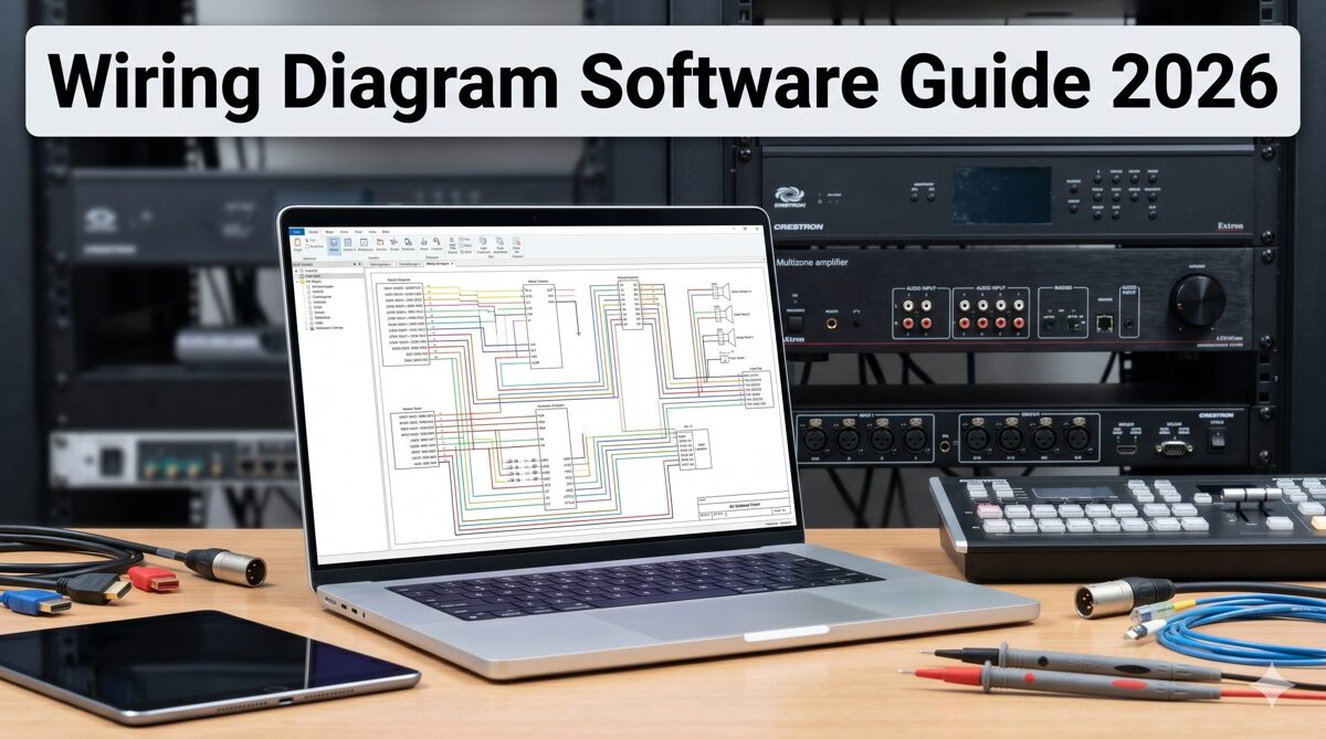
What Is AV Wiring Diagram Software?
AV wiring diagram software represents specialized digital platforms purpose-built to create comprehensive technical documentation specifically for audiovisual installations, incorporating industry-specific intelligence, automation capabilities, and workflow optimization designed around how AV system integrators actually design, specify, and document commercial AV projects. These platforms fundamentally differ from generic technical drawing tools by incorporating deep understanding of audiovisual equipment, signal routing, rack mounting, cable management, and system integration requirements unique to the AV industry.
Modern AV-specific diagram platforms function as intelligent design environments rather than simple drawing tools. They maintain equipment databases with manufacturer specifications, understand signal compatibility between devices, calculate rack space requirements automatically, validate power distribution, and generate multiple documentation views from single data models. This intelligence layer transforms documentation creation from manual drafting to automated generation driven by design intent and equipment selection.
Core Capabilities of AV-Specific Platforms
Professional AV wiring diagram software provides integrated capabilities addressing complete integration workflows:
Manufacturer equipment libraries containing 10,000-15,000 pre-built device models with accurate dimensions, connectors, and specifications
Automated rack layout generation producing elevation drawings directly from bill of materials data
Intelligent signal routing understanding audio, video, control, and network protocols
Integrated BOM management where equipment specified once populates all relevant documentation
Automatic cable labeling and schedule generation from signal flow data
Multi-format export to PDF, AutoCAD, Visio, SVG, and HTML with format optimization
Cloud-based collaboration enabling distributed team coordination and real-time synchronization
AI-assisted design providing equipment recommendations, layout optimization, and error detection
Project templates for common system configurations accelerating design initiation
Revision automation propagating changes across all affected documentation simultaneously
Industry-Specific Intelligence
What distinguishes AV wiring diagram platforms from generic tools is embedded industry knowledge:
Signal flow logic: Understanding that HDMI sources connect to video switchers, audio processors route to amplifiers, and control processors command system devices—automatically validating appropriate connections.
Equipment compatibility: Knowing that 4K60 4:4:4 signals require 18Gbps-capable HDMI cables, Dante audio needs gigabit network switches, and PoE devices must connect to powered network ports—preventing specification errors.
Rack mounting standards: Calculating that 2RU devices consume two rack units, equipment weight affects rack stability, and thermal management requires spacing between heat-generating components—optimizing physical layouts.
AV workflow integration: Recognizing that procurement, installation, commissioning, and maintenance teams all require different documentation views from the same system data—generating appropriate outputs for each stakeholder.
What Are Traditional CAD Tools?
Traditional CAD (Computer-Aided Design) tools represent general-purpose technical drawing platforms developed primarily for mechanical engineering, electrical design, architectural drafting, and product development—disciplines where precise geometric representation and dimensional accuracy take priority over industry-specific intelligence or workflow automation. These platforms treat all drawing tasks generically, providing powerful but complex drafting tools without inherent understanding of audiovisual systems, signal routing, or AV integration workflows.
CAD platforms like AutoCAD, AutoCAD Electrical, SolidWorks Electrical, DraftSight, and LibreCAD excel at creating precise technical drawings for manufacturing, construction, and engineering projects. They provide sophisticated geometry tools, dimensioning capabilities, layer management, block libraries, and programming interfaces enabling extensive customization for specific industries. However, this power comes with complexity—CAD systems require significant training investment and extensive customization to serve AV integration workflows effectively.
Core Capabilities of Traditional CAD Platforms
General-purpose CAD tools provide broad technical drawing capabilities:
Geometric drawing tools (lines, arcs, circles, polygons) for precise shape creation
Dimensioning systems with tolerance specifications and measurement standards
Layer management organizing drawing elements by function or discipline
Block libraries storing reusable symbols (requires manual creation for AV equipment)
Parametric modeling where dimensions drive geometry relationships
Drawing templates establishing sheet layouts and title blocks
Plot/print management for physical drawing output
File format support for industry-standard DWG and DXF formats
Programming interfaces (LISP, VBA, .NET) enabling custom automation
3D modeling capabilities (in advanced versions) for product visualization
Generic Architecture Requiring Customization
CAD platforms approach AV documentation as generic technical drawing requiring extensive manual customization:
No equipment intelligence: CAD treats an audio DSP identically to a mechanical component—requiring designers to manually create accurate representations with connector locations, rack mounting details, and dimensional specifications.
No signal flow logic: CAD cannot validate whether proposed equipment connections are technically feasible—designers must manually ensure signal compatibility, cable specifications, and routing appropriateness.
No workflow integration: CAD provides drawing tools but no BOM linkage, cable schedule automation, multi-view generation, or procurement integration—every document exists independently requiring manual coordination.
Generic symbol libraries: Standard CAD libraries contain electrical, mechanical, and architectural symbols but minimal AV-specific content—firms must invest 50-100 hours building custom equipment libraries or purchase third-party symbol collections.
Free vs Commercial CAD Options
Traditional CAD landscape includes both commercial platforms and free alternatives:
Commercial CAD (AutoCAD, AutoCAD Electrical, SolidWorks Electrical):
Professional-grade capabilities with extensive features
Industry-standard file formats ensuring universal compatibility
Robust technical support and comprehensive training resources
Expensive licensing ($1,500-3,000 annually per user)
Steep learning curves requiring 3-6 months for proficiency
Free CAD alternatives (LibreCAD, FreeCAD, DraftSight Free, QCAD):
Basic 2D drafting capabilities suitable for simple drawings
Limited feature sets compared to commercial platforms
Minimal technical support (community forums only)
Compatibility challenges with industry-standard formats
Adequate for basic block diagrams but insufficient for detailed AV documentation
For AV integrators evaluating free wiring diagram software, free CAD tools provide basic drawing capabilities but lack the automation, intelligence, and efficiency required for competitive commercial AV projects.
AV Wiring Diagram Software vs Traditional CAD Tools: Side-by-Side Comparison
Understanding the fundamental differences between purpose-built AV platforms and traditional CAD tools clarifies why increasing numbers of AV integrators transition away from generic CAD workflows despite the learning investment required.
Design Philosophy and Architecture
AV-Specific Software: Built around AV integration workflows, these platforms embed industry knowledge into software architecture. They understand equipment types, signal routing, rack mounting, and installation requirements—automating tasks based on this intelligence.
Traditional CAD: Designed as general-purpose technical drawing tools applicable across industries. They provide powerful drafting capabilities but no inherent AV-specific knowledge—requiring extensive manual work and customization for audiovisual applications.
Equipment Libraries and Symbol Management
AV-Specific Software: Includes 10,000-15,000 pre-built manufacturer device models with accurate dimensions, connector configurations, rack mounting specifications, and technical parameters. New equipment requires seconds to find and place.
Traditional CAD: Contains minimal AV equipment symbols. Firms must spend 50-100 hours building custom device libraries or purchase third-party collections. Each new device requires 15-30 minutes of manual symbol creation.
Rack Layout Creation
AV-Specific Software: Automated rack generation from BOM data produces complete elevation drawings in 5-10 minutes. Software calculates RU requirements, optimizes device positioning, considers thermal management, and generates front/rear views automatically.
Traditional CAD: Manual rack drawing requires 3-4 hours per project. Designers individually place equipment symbols, measure spacing, add dimensions, label devices, and create separate front/rear views. No automation or intelligence assists the process.
Signal Flow Diagram Creation
AV-Specific Software: Intelligent routing engines understand signal compatibility and suggest appropriate connections. Automated cable type recommendations match signal characteristics. Validation engines flag incompatible configurations. Time required: 15-30 minutes.
Traditional CAD: Entirely manual line drawing connecting equipment. No signal intelligence or validation. Designers must manually research and specify appropriate cable types for each connection. No compatibility checking occurs. Time required: 2-3 hours.
Cable Management and Labeling
AV-Specific Software: Automatic cable labeling following firm conventions, cable type specification based on signals, length calculation from routing, schedule generation with all connection details. Produces printable label sheets. Time required: automatic.
Traditional CAD: Completely manual cable schedule creation in separate documents (often Excel). Manual label assignment, type specification, and length estimation. No automation or integration with drawings. Time required: 1-2 hours.
BOM Integration and Equipment Coordination
AV-Specific Software: Single-source-of-truth architecture where equipment specified once in BOM automatically populates all diagrams. Changes propagate automatically. Procurement documents stay synchronized with technical drawings.
Traditional CAD: No BOM integration. Equipment must be entered separately in BOMs (usually Excel), rack drawings, signal flows, and cable schedules. Changes require manual updates in every document. Inconsistencies are common.
Multi-View Documentation Generation
AV-Specific Software: Automated generation of front elevations, rear elevations, side profiles, and 3D visualizations from single equipment models. All views stay synchronized as designs change.
Traditional CAD: Each view requires separate manual drawing. Maintaining consistency across views demands careful coordination. Changes must be manually replicated in every affected view.
Collaboration and Version Control
AV-Specific Software: Cloud-based platforms with real-time synchronization, multi-user editing, automatic version control, comment threading, and approval workflows. Distributed teams collaborate seamlessly.
Traditional CAD: File-based workflows requiring email sharing or network folders. Manual version tracking through file naming. Merge conflicts when multiple users edit. Difficult coordination across distributed teams.
Learning Curve and Training Requirements
AV-Specific Software: 3-5 days to basic proficiency, 2-3 weeks to mastery. Intuitive interfaces designed for AV professionals rather than CAD specialists. Most designers productive within first week.
Traditional CAD: 3-6 months to proficiency in CAD fundamentals plus 1-2 months customizing for AV workflows. Steep learning curves requiring significant training investment. Many firms must hire dedicated CAD operators.
Export and File Format Compatibility
AV-Specific Software: One-click export to PDF, AutoCAD DWG, Visio VSDX, SVG, PNG, XML, HTML with automatic format optimization. Ensures stakeholder compatibility without manual conversion.
Traditional CAD: Native DWG/DXF format with manual export to other formats. Converting to PDF or Visio requires format adjustments and quality verification. Often produces suboptimal results in non-native formats.
AI and Automation Capabilities
AV-Specific Software: AI-powered equipment recommendations, automated layout optimization, predictive error detection, intelligent design suggestions, natural language processing for requirements analysis.
Traditional CAD: Minimal or no AI capabilities. Some advanced platforms include basic automation through programming but requires custom development. No built-in AV-specific intelligence.
Cost Structure and Total Ownership
AV-Specific Software: Subscription pricing ($250-400/month per user) including continuous updates, cloud infrastructure, technical support, and feature improvements. Break-even ROI typically within 2-3 months through efficiency gains.
Traditional CAD: Perpetual licenses ($1,500-3,000 initial purchase) plus annual maintenance ($300-600) or subscription models ($1,500-2,500 annually). Free versions available but extremely limited. Higher costs when factoring in customization time and training investment.
Feature Comparison Table: AV Wiring Diagram Software vs CAD Tools
Feature/Capability | AV-Specific Software (X-DRAW) | Commercial CAD (AutoCAD) | Free CAD (LibreCAD) |
Equipment Library Size | 15,000+ pre-built AV devices | Minimal (requires custom creation) | None (all custom) |
Rack Layout Automation | ✅ Automatic generation (5-10 min) | ❌ Manual creation (3-4 hours) | ❌ Manual creation (3-4 hours) |
Signal Flow Intelligence | ✅ Intelligent routing & validation | ❌ Manual line drawing only | ❌ Manual line drawing only |
BOM Integration | ✅ Fully integrated & synchronized | ❌ No integration (manual coordination) | ❌ No integration |
Cable Management | ✅ Automatic labeling & schedules | ❌ Manual schedule creation | ❌ Manual schedule creation |
Multi-View Generation | ✅ Automatic from single model | ❌ Manual creation of each view | ❌ Manual creation of each view |
Cloud Collaboration | ✅ Real-time multi-user editing | ⚠️ Limited (requires Autodesk cloud) | ❌ File-based only |
AI-Assisted Design | ✅ Equipment recommendations & optimization | ❌ No AI capabilities | ❌ No AI capabilities |
Learning Curve | 3-5 days to proficiency | 3-6 months to proficiency | 2-4 months to proficiency |
Export Formats | PDF, DWG, Visio, SVG, PNG, XML, HTML | DWG native, PDF export | DXF native, limited exports |
Project Templates | ✅ AV-specific templates included | ⚠️ Generic templates (customization required) | ⚠️ Basic templates only |
Revision Automation | ✅ Automatic propagation across documents | ❌ Manual updates in each drawing | ❌ Manual updates in each drawing |
Mobile Access | ✅ Full mobile app support | ⚠️ Limited mobile viewer | ❌ No mobile support |
Technical Support | Comprehensive with AV expertise | Standard CAD support (no AV focus) | Community forums only |
Annual Cost | $3,000-4,800/user | $1,800-2,500/user | $0 |
Setup/Customization Time | 1-2 hours (out-of-box ready) | 50-100 hours (extensive customization) | 50-100 hours (library creation) |
Documentation Time (typical project) | 2-3 hours | 15-20 hours | 15-25 hours |
Time Savings vs Manual | 70-80% reduction | 10-20% reduction | 0-10% reduction |
Best For | Commercial AV integrators | Multi-discipline design firms | Hobbyists, basic diagrams |
Key Insights from Comparison
Automation gap: AV-specific platforms automate 70-80% of documentation tasks while CAD tools remain largely manual, creating dramatic efficiency differences.
Intelligence advantage: Purpose-built AV software understands equipment, signals, and workflows—enabling validation and optimization impossible with generic tools.
Total cost paradox: While AV platforms cost more monthly ($250-400 vs $150-200 for CAD), they save 12-18 hours per project. At typical designer rates ($75-125/hour), monthly subscription costs are recovered after 1-2 projects through labor savings.
Free tool limitations: Free CAD software appears cost-effective but requires 5-8x more labor time than AV-specific platforms, making them expensive in total project costs despite $0 licensing fees.
Why Many AV Integrators Are Moving Away from Traditional CAD Workflows
The AV integration industry is experiencing a significant migration from traditional CAD platforms to purpose-built AV software, driven by compelling operational and competitive factors reshaping how successful firms approach technical documentation.
Unsustainable Time Requirements for Manual Documentation
Commercial AV projects requiring 15-20 hours of CAD-based documentation create capacity constraints limiting firm growth. When senior designers earning $75-125/hour spend three days per project on drawings, that represents $1,800-3,000 in unrecoverable labor costs plus three lost days for additional projects. Automated platforms reducing this to 2-3 hours slash documentation costs to $150-375 while enabling designers to handle 3-4x more concurrent work—transforming business economics.
Competitive Pressure from Faster Proposal Response Times
RFP deadlines compressed to 5-7 days or less favor firms with efficient documentation workflows. Integrators using automated platforms can complete technical submissions in 24-48 hours while CAD-dependent competitors require a full week—often missing deadlines entirely. This speed advantage directly influences win rates in competitive bid environments where all qualified firms submit similar technical solutions.
Increasing System Complexity Overwhelming Manual Approaches
Modern AV installations incorporating 100-200+ devices across audio processing, video distribution, control systems, collaboration platforms, and network infrastructure create exponentially more complex documentation requirements. Manual CAD workflows that handled simpler projects adequately become unmanageable at scale, consuming 40-80 hours for enterprise installations. Automated platforms handle complexity through intelligent data management rather than linear drawing multiplication.
High Error Rates from Manual Specification and Drawing
Field installation errors caused by CAD documentation mistakes—incorrect connector specifications, mismatched cable labels, wrong rack dimensions, outdated equipment models—cost thousands in rework labor and project delays. Studies show manually created CAD drawings contain specification errors in 15-25% of projects versus 2-5% for automated platforms with validation engines. This error differential dramatically affects project profitability.
Difficulty Recruiting and Retaining CAD-Skilled AV Designers
The talent pool of AV professionals with advanced CAD expertise remains small and expensive. Requiring CAD proficiency excludes talented AV technicians and system designers from documentation roles, forcing firms to hire dedicated CAD operators or expensive consultants. Intuitive AV platforms enable AV experts to create documentation directly without CAD specialization—broadening available talent and improving knowledge transfer from field experience to documentation.
Cost and Complexity of CAD Software Customization
Achieving AV-optimized workflows in generic CAD platforms requires 50-100 hours of customization: building equipment libraries, creating templates, programming automation routines, and developing workflows. This represents $4,000-12,500 in development costs (at $80-125/hour for CAD specialists) before productivity improvements materialize. Purpose-built AV platforms provide these capabilities out-of-box, eliminating customization investment.
Limited Collaboration Capabilities for Distributed Teams
CAD file-based workflows struggle with distributed team collaboration—common in 2026 with remote designers, offshore drafters, and multi-office operations. Version conflicts, file synchronization issues, and merge challenges waste 3-5 hours weekly per designer. Cloud-based AV platforms solve these problems natively through real-time synchronization and automatic version control, making distributed teams as productive as co-located groups.
Inability to Validate Designs Before Procurement
CAD tools provide no technical validation—they'll happily produce drawings specifying incompatible equipment, impossible cable lengths, overloaded power circuits, or physically impossible rack configurations. Problems surface during installation when correction costs are maximum. AV-specific platforms with validation engines catch these issues during design when specification changes are simple and inexpensive.
Lack of Mobile and Field Access
CAD software remains desktop-centric, making documentation inaccessible to field technicians during installation. Technicians reference outdated PDF printouts rather than current designs, causing communication breakdowns and installation errors. Cloud AV platforms with mobile apps provide installers real-time access to latest documentation plus ability to mark up as-built modifications directly.
Key Benefits of AV Wiring Diagram Software for Integrators
Transitioning from traditional CAD workflows to purpose-built AV platforms delivers measurable advantages across operational efficiency, competitive positioning, project quality, and business scalability.
Dramatic Time Savings and Capacity Multiplication
AV-specific platforms reduce documentation time by 60-80%—enabling designers to complete in 2-3 hours what CAD workflows require 15-20 hours to produce. This efficiency gain multiplies designer capacity 3-4x, allowing firms to handle more projects with existing teams or redirect designer time toward higher-value activities like client consultation and system architecture development.
Capacity impact: A designer completing one detailed conference room project weekly using CAD can handle three to four comparable projects simultaneously with automated platforms—tripling productive output without working longer hours.
Superior Documentation Quality and Consistency
Automated generation from equipment databases eliminates human errors in dimensions, specifications, and calculations that plague manual CAD drawings. Validation engines catch compatibility issues before procurement. Template-based workflows ensure consistent formatting across all projects and designers. This quality advantage improves client perception, reduces field corrections, and enhances firm reputation.
Reduced Field Errors and Installation Rework
Projects documented in AV-specific platforms with validation engines experience 80-90% fewer field errors compared to manual CAD workflows. Automated cable labeling prevents wiring mistakes. BOM synchronization ensures installed equipment matches documentation. Multi-view generation provides installers comprehensive guidance. These improvements protect project margins by minimizing costly rework labor.
Faster Proposal Development and Improved Win Rates
Template-based rapid design, automated rack generation, and one-click export enable proposal completion in 24-48 hours versus the week required with CAD workflows. This response speed increases bid participation (accepting opportunities competitors must decline) and improves win rates (being first to submit influences selection). Comprehensive documentation also demonstrates firm sophistication differentiating proposals.
Scalable Growth Without Proportional Staffing
Efficiency gains from automated platforms enable revenue growth without proportional designer hiring. When existing designers can handle 3-4x more work, firms scale operations while improving margins rather than simply maintaining them through volume. This operational leverage proves particularly valuable during rapid growth or economic uncertainty requiring staffing flexibility.
Improved Designer Satisfaction and Retention
Talented AV designers prefer solving interesting technical problems over spending hours manually drafting rack elevations and typing cable schedules. Automated platforms eliminating tedious tasks improve job satisfaction, help retain top talent, and attract better candidates during hiring. Reduced stress from eliminating overtime and deadline pressure also contributes to healthier work environments.
Enhanced Client Communication and Satisfaction
Professional documentation with consistent formatting, 3D visualizations, and comprehensive detail creates positive client impressions. Fast revisions responding to client changes same-day demonstrate responsiveness. Interactive documentation via cloud portals provides clients unprecedented project transparency. These factors strengthen client relationships, drive repeat business, and generate referrals.
Better Collaboration Across Distributed Teams
Cloud-based platforms with real-time synchronization enable seamless collaboration between in-house designers, remote consultants, offshore drafters, and field technicians. Version control automation eliminates confusion about current design states. Comment threading facilitates communication without email chains. Role-based access provides stakeholders appropriate visibility. These capabilities make distributed teams as productive as co-located groups.
Comprehensive Project Documentation Archives
Cloud storage with automatic backups ensures project documentation never gets lost due to hard drive failures, desktop crashes, or accidental deletions. Historical project access enables designers to reference past successful installations when designing similar new projects. Client portal integration provides customers lifetime access to as-built documentation supporting their facility management needs.
Competitive Differentiation in Saturated Markets
As more AV integration firms adopt advanced documentation platforms, those still using traditional CAD increasingly appear outdated to sophisticated clients. Superior documentation quality, faster response times, and comprehensive deliverables differentiate firms in crowded markets where technical capabilities are otherwise similar. Documentation excellence becomes a competitive weapon.
Best AV Wiring Diagram Software for Integrators in 2026
The following platforms represent leading solutions available to AV integrators as of June 2026, with emphasis on automation depth, AV-specific optimization, and practical value for commercial firms.
1. XTEN-AV X-DRAW
XTEN-AV's X-DRAW stands as the most sophisticated purpose-built platform for audiovisual integration documentation, delivering unmatched automation capabilities, comprehensive AV intelligence, and workflow optimization specifically engineered for commercial AV system integrators rather than adapted from generic tools.
X-DRAW represents a ground-up reimagining of AV documentation centered on three principles: maximum automation, embedded AV intelligence, and seamless workflow integration. Unlike CAD platforms that provide generic drawing tools, X-DRAW functions as an intelligent design assistant that understands audiovisual equipment, signal routing, installation requirements, and industry best practices—actively participating in design rather than passively recording it.
Developed by former AV integrators who experienced CAD workflow frustrations firsthand, X-DRAW eliminates pain points systematically through targeted automation. The platform has documented tens of thousands of commercial installations since launch, continuously refining capabilities based on real-world usage patterns and user feedback from hundreds of AV integration firms.
Key Features Demonstrating AV Specialization
Automated Rack Layout Generation: X-DRAW's flagship feature generates complete rack elevation drawings from BOM equipment with one-click operation. What requires 3-4 hours in CAD completes in 5-10 minutes. The automation engine calculates RU requirements, optimizes device positioning considering thermal management and weight distribution, places power distribution units strategically, and generates front/rear elevations simultaneously—producing installation-ready documentation without manual drawing.
Intelligent Rack Elevation Diagrams: Beyond basic layouts, X-DRAW generates sophisticated elevations incorporating airflow analysis, cable routing suggestions, power consumption calculations, weight distribution charts, and maintenance access indicators. These details that experienced designers would spend 45-60 minutes adding manually appear automatically in X-DRAW-generated diagrams.
Integrated BOM-to-Rack Workflow: X-DRAW's single-source-of-truth architecture eliminates duplicate data entry. Equipment added to project BOMs instantly becomes available for rack assignment, signal flow inclusion, cable schedule population, and equipment specification sheets. This integration saves 2-3 hours per project while ensuring perfect consistency between procurement documents and technical drawings.
AV-Specific Design Automation: X-DRAW includes built-in automation unavailable in CAD platforms: automatic signal routing between compatible devices, cable type recommendations matching signal characteristics, connector validation ensuring physical compatibility, format conversion identification where needed, control system programming structure generation, and network addressing planning.
Front Elevation and Rack Documentation: X-DRAW automatically generates multiple documentation views—front elevations showing user-facing equipment, rear elevations depicting technician connections, side profiles illustrating depth and clearances, and 3D visualizations for client presentations. All views stay synchronized as designs change, eliminating manual coordination required in CAD workflows.
Extensive Product Library: X-DRAW provides 15,000+ pre-built AV device models from hundreds of manufacturers with accurate dimensional specifications, detailed connector configurations, technical specifications, manufacturer part numbers, 3D models for visualization, and installation requirements. This eliminates 30-60 minutes per project creating custom symbols required with CAD tools.
Customizable Device Blocks and Connectors: For specialty equipment not in libraries, X-DRAW provides semi-automated creation tools with template-based workflows, automatic connector positioning, symbol generation from equipment photos, and specification extraction from manufacturer data sheets. Custom symbol creation that requires 45-60 minutes in CAD completes in 15-20 minutes in X-DRAW.
Automatic Cable Labeling and Signal Management: X-DRAW's comprehensive cable automation generates sequential cable numbers, both-end labels, cable type specifications, length calculations, complete cable schedules, printable label sheets, and color coding—eliminating 1-2 hours of manual work per project.
Export to Multiple Formats: X-DRAW's one-click export produces stakeholder-appropriate formats: PDF with embedded metadata, AutoCAD DWG maintaining layers, Microsoft Visio VSDX with editable objects, SVG vector graphics, PNG raster images, XML data exports, and HTML interactive packages. This automation saves 1-2 hours of manual file conversion per project.
Cloud-Based Collaboration: X-DRAW's cloud architecture enables real-time synchronization across team members, automatic conflict resolution when editing simultaneously, version control automation, comment threading on diagram elements, approval workflow automation, and role-based access control. This eliminates 3-5 hours weekly on file management overhead.
AI-Assisted Drawing Capabilities: X-DRAW incorporates artificial intelligence for equipment recommendations based on project requirements, layout optimization suggesting improvements, error detection flagging compatibility issues, design refinement polishing diagram quality, requirements extraction from client documents, and automated design generation from specifications.
Faster Revisions and Project Updates: When requirements change, X-DRAW's revision automation propagates updates across all affected diagrams, recalculates BOMs, adjusts cable schedules, updates rack layouts, regenerates exports, and tracks changes in revision history—completing in minutes what CAD workflows require hours to accomplish.
Pros of X-DRAW
✅ Industry-leading automation reducing documentation time by 70-80% ✅ Comprehensive AV intelligence built into platform architecture ✅ 15,000+ device library eliminating custom symbol creation ✅ Automated rack generation saving 3-4 hours per project ✅ BOM integration ensuring documentation consistency ✅ Cloud collaboration enabling distributed teams ✅ AI assistance providing intelligent recommendations ✅ Multi-format export with automatic optimization ✅ 3-5 day learning curve versus 3-6 months for CAD ✅ Break-even ROI within 2-3 months
Cons of X-DRAW
❌ Subscription cost of $300-400/month per user ❌ Internet connectivity required for cloud platform ❌ Process changes from traditional CAD workflows ❌ Learning investment to master advanced features
Best For
X-DRAW excels for commercial AV integration firms, corporate system designers, educational technology consultants, government contractors, healthcare AV specialists, and any integrators prioritizing maximum efficiency, documentation quality, and competitive positioning through technological advantage.

2. AutoCAD Electrical
AutoCAD Electrical extends Autodesk's CAD platform with electrical design capabilities applicable to AV documentation but requires extensive customization for AV workflows.
Key Features
Automated wire numbering for cable identification
Component tagging and BOM generation
PLC integration for control systems
Electrical symbol libraries (requires AV customization)
Industry-standard DWG format
Pros/Cons
✅ Universal compatibility, powerful customization ❌ Not AV-optimized, steep learning curve, expensive ($2,000-3,000/year)
Best For
Multi-discipline firms with CAD specialists, projects requiring architectural coordination, large integrators already standardized on Autodesk ecosystems.
3. D-Tools System Integrator
D-Tools SI combines project management and documentation with moderate AV-specific features but less automation depth than specialized platforms.
Key Features
Integrated business management spanning sales to installation
Automated BOM generation with manufacturer pricing
Basic rack layout capabilities
Proposal creation with templates
Pros/Cons
✅ Unified platform, AV industry focus, established community ❌ Limited automation vs. X-DRAW, expensive, desktop-centric
Best For
Integration firms seeking unified business management, residential integrators, organizations prioritizing sales workflows over detailed technical documentation.
4. Free CAD Options (LibreCAD, DraftSight Free)
Free CAD software provides basic 2D drafting adequate for simple diagrams but lacks automation, AV intelligence, and efficiency required for commercial work.
Key Features
Basic line drawing and geometric tools
Simple layer management
DXF file format support
Community support only
Pros/Cons
✅ Zero licensing cost ❌ No automation, no AV libraries, minimal features, 15-25 hours per project documentation time
Best For
Hobbyists, students, basic block diagrams, budget-constrained scenarios where time efficiency isn't critical.
Common Mistakes Integrators Make When Choosing Design Software
Avoiding these selection errors ensures AV integrators choose platforms supporting long-term business objectives rather than creating new constraints.
Mistake 1: Prioritizing Free Tools Over Total Cost of Ownership
Free wiring diagram software like LibreCAD appears cost-effective until accounting for labor inefficiency. A designer spending 15-20 hours per project on free CAD costs $1,125-2,500 in labor (at $75-125/hour) versus 2-3 hours in specialized platforms costing $150-375. The "$0 software" actually costs $975-2,125 more per project in total expenses.
Solution: Evaluate total project costs including labor time rather than just software licensing fees.
Mistake 2: Assuming CAD Skills Transfer Directly to AV Efficiency
CAD proficiency helps but doesn't automatically deliver AV workflow efficiency. Even experienced CAD users spend 3-4 hours on rack layouts that AV-specific platforms complete in 5-10 minutes because CAD lacks automation and AV intelligence.
Solution: Evaluate platforms based on AV-specific capabilities and workflow optimization rather than existing CAD expertise.
Mistake 3: Underestimating Learning Curve and Productivity Loss
Firms often underestimate transition periods when switching platforms. CAD platforms require 3-6 months to proficiency, creating significant productivity dips during learning. AV-specific platforms with 3-5 day learning curves minimize disruption.
Solution: Factor learning time and transition productivity into platform selection decisions.
Mistake 4: Overlooking Collaboration and Remote Work Requirements
File-based CAD workflows create collaboration challenges increasingly important with distributed teams. Choosing desktop-centric tools in 2026 ignores reality that teams work remotely, projects involve distributed stakeholders, and cloud collaboration is table stakes.
Solution: Prioritize cloud-based platforms with real-time collaboration capabilities supporting distributed work.
Mistake 5: Failing to Calculate ROI and Break-Even Timelines
Many integrators make platform decisions based on monthly costs without calculating ROI. A $350/month specialized platform that saves 12 hours per project pays for itself after one project at typical designer rates—achieving break-even within 2-3 months.
Solution: Calculate monthly labor savings from efficiency gains versus subscription costs to determine actual ROI.
Mistake 6: Choosing Based on Marketing Claims Rather Than Trial Experience
Software vendors make impressive claims that may not match real-world performance. Selecting platforms without hands-on trials risks discovering limitations after commitment.
Solution: Conduct hands-on trials with representative projects before committing to platforms.
Mistake 7: Ignoring Integration with Existing Business Systems
Platforms that don't integrate with CRM, accounting, project management, or procurement systems create ongoing manual work transferring data between systems.
Solution: Evaluate API capabilities and integration ecosystem supporting complete business workflows.
Frequently Asked Questions
Q: Is free wiring diagram software adequate for professional AV integration work?
Free CAD tools like LibreCAD provide basic drawing capabilities but lack automation, AV intelligence, and efficiency required for competitive commercial work. The 15-25 hours per project they require versus 2-3 hours with specialized platforms makes them far more expensive in total project costs despite $0 licensing.
Q: How much faster is AV-specific software compared to traditional CAD?
Purpose-built AV platforms like X-DRAW reduce documentation time by 60-80%, completing in 2-3 hours what CAD workflows require 15-20 hours to produce. This represents 3-4x capacity multiplication for designers.
Q: Can traditional CAD tools be customized to match AV-specific platforms?
Partially, but requires 50-100 hours of customization ($4,000-12,500 in development costs) to achieve even basic AV functionality—and still lacks intelligence, validation, and advanced automation that purpose-built platforms provide natively.
Q: What's the learning curve difference between CAD and AV-specific software?
Traditional CAD requires 3-6 months to proficiency while AV-specific platforms need only 3-5 days for basic skills and 2-3 weeks for mastery. Most designers achieve break-even productivity within their first week using AV platforms.
Q: Do cloud-based platforms work without internet connectivity?
Most cloud platforms require internet connectivity for full functionality, though many offer offline modes with limited capabilities. The collaboration benefits and automatic backups typically outweigh occasional connectivity inconvenience.
Q: How do subscription costs compare to perpetual CAD licenses?
AV platforms ($3,000-4,800 annually per user) cost more than perpetual CAD amortized over 5 years but deliver 500-700 hours annual time savings worth $37,500-87,500 in labor costs—making them dramatically more cost-effective in total value.
Q: Can firms transition from CAD to AV-specific software mid-project?
Most firms complete platform transitions within 2-4 weeks using parallel workflows (completing current projects in CAD while starting new projects in new platforms). This approach minimizes disruption while accelerating capability improvements.
Conclusion
The comparison between traditional CAD tools and purpose-built AV wiring diagram software reveals fundamental architectural differences that dramatically impact operational efficiency, project profitability, and competitive positioning for audiovisual integration firms in mid-2026. While free wiring diagram software and generic CAD platforms initially appear cost-effective, the hidden expenses of inefficient workflows, extended project timelines, increased error rates, and limited scalability make them far more expensive than specialized platforms like XTEN-AV's X-DRAW when evaluating total cost of ownership.
X-DRAW's industry-leading 70-80% time savings—reducing typical documentation from 15-20 hours to 2-3 hours—transforms business economics by enabling designers to handle 3-4x more concurrent projects without working longer hours. This capacity multiplication proves impossible with traditional CAD workflows requiring extensive manual work for every rack elevation, signal flow diagram, and cable schedule. The automation depth, AV-specific intelligence, and workflow integration that purpose-built platforms provide simply cannot be replicated through CAD customization—no matter how much time and money firms invest in symbol libraries, templates, and programming.
The strategic choice between CAD and specialized AV software ultimately determines whether firms compete on low-price commoditization or high-value differentiation. CAD-dependent integrators face capacity constraints limiting growth, documentation quality that undermines professionalism, and competitive disadvantages against firms deploying advanced automation. Meanwhile, organizations embracing platforms like X-DRAW gain operational leverage enabling profitable scaling, superior deliverables enhancing reputation, and efficiency advantages winning competitive projects.
As the AV integration industry continues evolving throughout 2026 and beyond, the gap between firms using modern automation platforms and those clinging to traditional CAD will only widen. The documented performance advantages—70-80% time savings, 3-4x capacity multiplication, 80-90% error reduction, 2-3 month ROI—make the decision mathematically clear for firms serious about competitive positioning and sustainable growth. The question isn't whether to adopt specialized AV documentation platforms—it's how quickly to implement before competitive disadvantages become insurmountable.
How to Organize AV Equipment in a Wall Mount Rack for Maximum Efficiency
Efficient equipment organization within a wall mount Audio Visual (AV) rack directly determines system reliability, maintenance efficiency, thermal performance, and overall installation quality. Poor rack organization creates cascading problems—from equipment overheating and cable management chaos to difficult troubleshooting and costly service callbacks. Professional AV integrators understand that strategic equipment placement, logical device sequencing, and systematic cable routing separate exceptional installations from mediocre ones.
Beyond basic equipment mounting, knowing how to mount Audio Visual (AV) rack on wall with optimal device organization requires understanding thermal dynamics, signal integrity, weight distribution, cable management principles, and maintenance accessibility. Properly organized racks enable technicians to quickly identify equipment, trace signal paths, diagnose issues, and perform system upgrades without disrupting adjacent devices—competencies essential for competitive AV integration firms.
This comprehensive guide provides AV integrators, system designers, and installation technicians with proven methodologies for organizing AV equipment within wall mount racks. From fundamental equipment sequencing principles through advanced cable management strategies and thermal optimization, these practical techniques ensure your rack deployments achieve maximum efficiency, reliability, and professional presentation.
Key Takeaways
Equipment organization in wall mount racks directly impacts system reliability, thermal performance, maintenance accessibility, and troubleshooting efficiency
Strategic equipment placement follows the principle: heavy devices bottom, heat-generating equipment near bottom, frequently accessed devices at optimal heights
Logical equipment sequencing based on signal flow reduces cable complexity and improves installation clarity
Weight distribution requires positioning heaviest equipment near rack bottom to minimize wall stress and prevent mounting failures
Thermal management demands adequate spacing (minimum 1U) between heat-generating devices and proper airflow planning
Cable organization begins with infrastructure installation before equipment mounting, not as an afterthought
Power distribution should be planned for balanced electrical loads, proper circuit utilization, and future expansion
Accessibility planning ensures frequently maintained equipment occupies positions allowing service without disturbing other devices
Labeling systems for both equipment and cables accelerate troubleshooting and reduce maintenance time
Modern AV design software like XTEN-AV's X-DRAW automates optimal equipment sequencing and rack organization planning
Documentation including detailed rack elevation diagrams and equipment inventories is essential for long-term system management
Proper organization reduces installation time, minimizes service callbacks, and improves client satisfaction
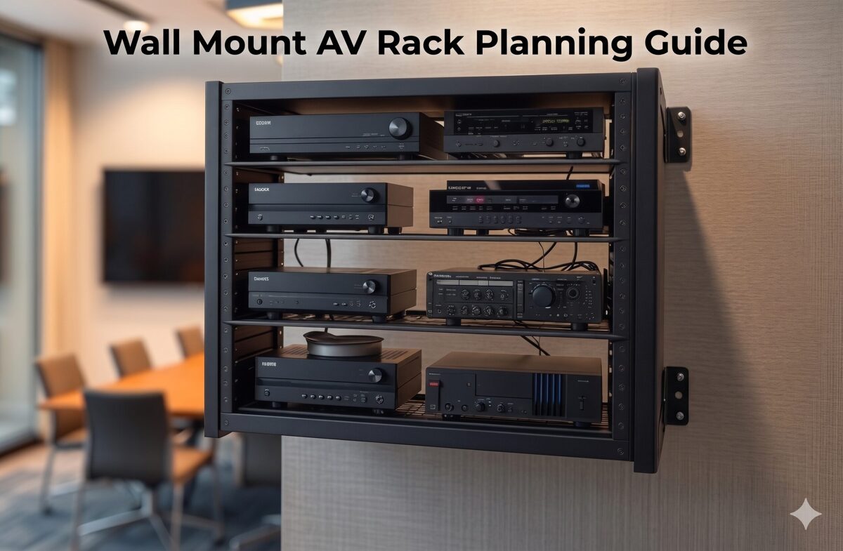
What Is a Wall Mount AV Rack?
A wall mount AV rack is a vertical equipment enclosure or mounting framework that attaches securely to wall surfaces while providing standardized mounting positions for rack-mountable AV equipment. These racks serve as the centralized housing for video processors, audio equipment, network switches, control systems, signal distribution, and power management devices.
Technical Foundation
Wall mount racks adhere to industry standards:
Rack Unit (RU or U) measurement: Each unit represents 1.75 inches (44.45mm) of vertical space
EIA-310-D or IEC 60297 compliance: Standardized mounting hole patterns and spacing
19-inch width: Universal standard between mounting rails ensuring equipment compatibility
Typical capacity: 6U-22U for wall-mounted applications (larger sizes become floor standing racks)
Depth variations: 12-24 inches accommodating different equipment dimensions
Organizational Components
Well-designed wall mount racks include:
Mounting rails: Vertical rails with threaded holes for equipment attachment
Cable management: Vertical cable managers, horizontal organizers, cable entry/exit provisions
Power distribution: Mounting locations for PDUs and electrical infrastructure
Ventilation: Perforated panels, fan mounting positions, airflow channels
Blank panels: Filler panels maintaining airflow control and professional appearance
Enclosure options: Open frame, vented enclosures, or solid enclosures based on security/cooling needs
Equipment Organization Context
Effective rack organization transforms these components into efficient AV system platforms by strategically positioning equipment to optimize thermal performance, cable management, maintenance access, and system reliability.
Why Proper AV Rack Organization Matters
Strategic equipment organization within wall mount racks impacts multiple critical factors beyond simple device mounting.
1. System Reliability and Equipment Longevity
Proper organization directly affects equipment lifespan:
Thermal optimization: Correct equipment spacing and heat distribution prevent thermal failures and extend component life
Vibration isolation: Separating mechanical equipment (fans, hard drives) from sensitive devices reduces vibration-induced failures
Electrical interference: Strategic device separation minimizes electromagnetic interference (EMI) affecting signal quality
Weight distribution: Proper load management prevents mounting stress and rack failures
2. Maintenance Efficiency and Reduced Downtime
Organized racks accelerate service workflows:
Quick equipment identification: Logical device placement enables technicians to rapidly locate specific components
Accessible connections: Well-planned equipment positioning allows cable access without removing multiple devices
Efficient troubleshooting: Clear signal flow organization helps technicians trace paths and diagnose issues
Reduced service time: Organized installations decrease maintenance duration and associated costs
3. Cable Management and Signal Integrity
Strategic equipment sequencing simplifies cable routing:
Shorter cable runs: Positioning related equipment adjacently reduces cable lengths and signal loss
Organized pathways: Logical equipment placement creates natural cable routing patterns
Reduced cable congestion: Proper device spacing prevents cable overcrowding and tangling
Signal quality: Appropriate equipment separation (e.g., power from signal devices) maintains signal integrity
4. Thermal Management and Cooling Efficiency
Equipment organization determines thermal performance:
Heat stratification: Positioning heat-generating equipment appropriately leverages natural heat rise
Airflow optimization: Strategic device placement creates effective cooling paths through rack
Hotspot prevention: Proper equipment spacing prevents localized heat accumulation
Cooling efficiency: Organized racks reduce cooling fan requirements and energy consumption
5. Professional Appearance and Client Confidence
Well-organized racks demonstrate installation quality:
Visual impact: Clean, organized equipment presentation impresses clients and builds confidence
Brand differentiation: Professional rack organization distinguishes quality integrators from competitors
Documentation quality: Organized systems photograph better for portfolio and marketing materials
Client perception: Neat installations suggest attention to detail and system reliability
6. Future Expansion and System Scalability
Thoughtful organization accommodates growth:
Reserved space: Planned equipment positioning leaves strategic rack units available for additions
Flexible routing: Organized cable infrastructure enables easy equipment additions
Power availability: Strategic PDU placement ensures outlets remain accessible for new devices
Documentation accuracy: Well-organized systems are easier to document, facilitating future modifications
7. Installation Efficiency and Cost Reduction
Strategic pre-planning of equipment organization reduces installation costs:
Faster deployment: Clear equipment placement plans accelerate installation workflows
Reduced errors: Pre-planned organization minimizes mounting mistakes requiring rework
Material optimization: Proper device sequencing reduces cable and hardware waste
Labor savings: Organized approaches reduce installation hours and associated costs
Common Problems Caused by Poor Rack Organization
Understanding failure modes helps AV integrators avoid costly mistakes and improve installation practices.
1. Thermal Failures and Equipment Overheating
Problem: Heat-generating equipment clustered together or positioned at rack top without adequate ventilation.
Consequences:
Equipment overheating causing thermal shutdowns during operation
Premature component failures reducing equipment lifespan
Intermittent system performance issues difficult to diagnose
Warranty voiding due to operating outside temperature specifications
Example: Three network switches mounted consecutively at rack top without spacing, each generating 150W, creating localized hotspot exceeding 140°F.
2. Cable Management Chaos
Problem: Equipment positioned without considering cable routing, creating cable congestion and disorganization.
Consequences:
Tangled cables making troubleshooting difficult and time-consuming
Cable stress at connection points causing intermittent failures
Difficulty tracing signal paths during diagnostics
Unprofessional appearance damaging client confidence
Airflow obstruction from cable masses blocking ventilation
Example: Video matrix switcher at rack bottom with displays connected throughout facility, requiring cables to run entire rack height through congested vertical managers.
3. Maintenance Accessibility Issues
Problem: Frequently serviced equipment positioned in locations requiring extensive disassembly to access.
Consequences:
Extended service times increasing maintenance costs
Higher risk of cable disconnection when moving equipment for access
Technician frustration leading to rushed work and potential errors
Increased system downtime during maintenance windows
Example: Media player requiring weekly content updates mounted behind cable management at rack top, necessitating ladder and cable routing disruption for every update.
4. Structural and Weight Distribution Problems
Problem: Heavy equipment concentrated at rack top or unevenly distributed side-to-side.
Consequences:
Excessive wall stress at upper mounting points risking failure
Rack tipping hazard during door opening or equipment access
Potential mounting bracket failures under unbalanced loads
Equipment damage if rack stability compromised
Example: 40-lb amplifier and 35-lb UPS mounted at rack top with lightweight switches below, creating top-heavy configuration stressing wall anchors.
5. Power Distribution Inefficiencies
Problem: PDU positioned inconveniently or power cords routed chaotically without planning.
Consequences:
Power cord congestion blocking equipment access and airflow
Excessive cord lengths creating cable management challenges
Difficult power cord tracing during troubleshooting
PDU outlet accessibility blocked by cable masses
Example: PDU mounted at rack top with all equipment below, requiring long power cords running full rack height, consuming cable manager space needed for signal cables.
6. Signal Flow Confusion
Problem: Equipment positioned randomly without following logical signal paths.
Consequences:
Difficult system understanding for maintenance technicians
Complex troubleshooting requiring extensive cable tracing
Higher risk of mis-wiring during installations or modifications
Poor documentation accuracy due to non-intuitive equipment layout
Example: Video source at rack bottom, switcher at top, distribution amplifier in middle, creating confusing signal flow and excessive cable crossings.
7. Future Expansion Limitations
Problem: Equipment densely packed without reserved rack space for anticipated growth.
Consequences:
Expensive rack replacement required for modest equipment additions
Complex equipment rearrangement to accommodate new devices
Temporary installations compromising system organization
Client frustration with limited scalability
Example: 12U rack filled completely during initial installation, requiring expensive rack replacement and complete system reinstallation when client adds video recording device six months later.
8. Documentation Discrepancies
Problem: Equipment installed differently than documented rack elevation diagrams.
Consequences:
Documentation becomes unreliable for future maintenance
Technicians waste time locating equipment not matching diagrams
System modifications based on incorrect documentation create errors
Knowledge loss when original installers unavailable
Example: Rack elevation shows equipment sequence, but installer reverses positions during deployment without updating documentation, confusing future service teams.
Step-by-Step Guide to Organizing AV Equipment in a Wall Mount Rack
This comprehensive methodology ensures optimal equipment organization from planning through deployment.
Phase 1: Pre-Planning and Equipment Assessment
Step 1: Create Complete Equipment Inventory
Develop detailed equipment list with critical specifications:
Essential Information:
Device name and model number
Rack unit height (RU) requirement
Equipment depth (front-to-rear dimension)
Weight (for load distribution planning)
Power consumption (watts) and heat generation (BTU/hr)
Connection requirements (input/output ports, quantity and type)
Cooling requirements (passive vs. active cooling needs)
Maintenance frequency (daily, weekly, monthly, rarely)
Example Inventory:
Equipment | RU | Depth | Weight | Power | Heat | Maintenance |
Video Matrix | 2U | 18" | 25 lbs | 150W | 512 BTU/hr | Rare |
Network Switch | 1U | 12" | 8 lbs | 75W | 256 BTU/hr | Occasional |
Control Processor | 1U | 10" | 5 lbs | 25W | 85 BTU/hr | Occasional |
Step 2: Analyze Signal Flow Paths
Map signal routing through equipment chain:
Identify all signal sources (cameras, computers, media players)
Trace signal path through processing equipment (switchers, scalers, distribution amplifiers)
Map signal destinations (displays, speakers, recording devices)
Document control system connections
Note network infrastructure requirements
Signal Flow Example:
Sources → Video Matrix Switcher → Distribution Amplifier → Displays
Control: Touch Panel → Control Processor → Serial/IP Control → Equipment
Step 3: Assess Thermal Characteristics
Categorize equipment by heat generation:
High-Heat Equipment (>100W/device):
Amplifiers
High-density network switches
Video processors with multiple outputs
Media servers and computers
Medium-Heat Equipment (50-100W/device):
Video switchers
Matrix switchers
Standard network switches
Power supplies
Low-Heat Equipment (<50W/device):
Control processors
Cable management panels
Patch panels
Distribution amplifiers
Step 4: Determine Maintenance Access Requirements
Classify equipment by service frequency:
Frequent Access (weekly or more):
Media players requiring content updates
Video sources with media insertion
Equipment with user-adjustable controls
Occasional Access (monthly or quarterly):
Network switches requiring port access
Control processors for programming updates
Equipment with firmware update needs
Rare Access (annual or less):
Video processors with stable configurations
Distribution equipment
Signal management devices
Phase 2: Strategic Equipment Sequencing
Step 5: Position Equipment by Weight Distribution
Organize devices vertically for optimal load management:
Bottom Section (Lower 1/3 of Rack):
Heaviest equipment (>20 lbs per device)
High-wattage amplifiers
UPS systems and power conditioning
Dense video processors
Middle Section (Center 1/3 of Rack):
Medium-weight equipment (10-20 lbs)
Network switches
Video switchers and matrices
Cable management panels
Top Section (Upper 1/3 of Rack):
Lightweight equipment (<10 lbs)
Control processors
Patch panels
Final cable management and blank panels
Weight Distribution Principle: Bottom-heavy configuration minimizes wall stress and prevents mounting failures.
Step 6: Sequence Equipment Following Signal Flow
Arrange devices in logical signal path order:
Option A: Top-to-Bottom Signal Flow
Sources at rack top
Processing equipment in middle
Distribution equipment at bottom
Advantage: Natural cable drop from sources through processing
Option B: Bottom-to-Top Signal Flow
Sources at rack bottom
Processing in middle
Distribution at top
Advantage: Sources accessible at lower heights
Best Practice: Choose approach minimizing cable length and complexity based on where signal sources physically connect (e.g., if sources connect from above rack, use top-to-bottom flow).
Step 7: Position Equipment by Thermal Characteristics
Organize for optimal heat management:
Heat Management Strategy:
Position highest-heat equipment near rack bottom (heat rises naturally)
Maintain minimum 1U spacing between high-heat devices
Alternate high-heat and low-heat equipment when possible
Reserve rack top area for cooling fan exhaust path
Install blank panels to direct airflow through equipment
Example Organization (12U Rack):
1-2U: Amplifier (high heat) at bottom
3U: Blank panel or cable manager (spacing)
4-5U: Video matrix (medium heat)
6-7U: Network switch (medium heat)
8U: Cable management (spacing)
9-10U: Control processor + patch panel (low heat)
11-12U: Blank panels (top ventilation space)
Step 8: Plan Equipment for Maintenance Accessibility
Position devices by service frequency:
Optimal Height Positioning (48-72 inches from floor = comfort zone):
Frequently accessed equipment at rack center (no ladder required)
Front-panel controls easily visible and reachable
Media insertion devices at convenient heights
Less Accessible Positions:
Rarely serviced equipment at rack bottom (below 48 inches)
Stable equipment at rack top (above 72 inches)
Equipment with remote management positioned for cable access priority
Step 9: Reserve Rack Space for Future Expansion
Strategically allocate unused rack units:
Expansion Planning:
Reserve 20-30% total rack capacity for growth
Position reserved space near related equipment (e.g., reserve 1-2U near video switching for additional input card)
Install blank panels in reserved positions maintaining airflow control
Document reserved space purpose in as-built drawings
Plan power and cooling capacity for future equipment
Phase 3: Create Detailed Rack Elevation Diagram
Step 10: Document Equipment Positions
Develop professional rack layout drawing:
Rack Elevation Components:
RU numbering (1U at bottom progressing upward)
Equipment names and model numbers at each position
Blank panel locations
Cable management panel positions
PDU location and type
Ventilation/cooling provisions
Documentation Tools:
Professional AV design software (XTEN-AV X-DRAW, Visio, AutoCAD)
Manual drafting with rack elevation templates
Spreadsheet-based rack planning tools
Step 11: Validate Organization Plan
Review equipment layout against criteria:
Validation Checklist:
☐ Weight distribution: Heaviest equipment at bottom
☐ Thermal management: Adequate spacing between high-heat devices
☐ Signal flow logic: Equipment sequence follows signal path
☐ Maintenance access: Frequently serviced equipment at optimal heights
☐ Cable routing: Equipment positions enable efficient cable management
☐ Future expansion: Reserved rack space for anticipated additions
☐ Power distribution: PDU position supports efficient power cord routing
☐ Total RU count: Equipment plus cable management fits within rack capacity
Phase 4: Equipment Installation Execution
Step 12: Install Cable Management Infrastructure First
Prepare cable routing before equipment mounting:
Install vertical cable managers on both rack sides
Pre-position horizontal cable organizers at planned locations
Mount cable entry/exit panels at rack top/bottom
Verify adequate cable routing depth behind equipment mounting area
Step 13: Mount Equipment Following Rack Elevation
Install devices systematically per documented plan:
Installation Sequence:
Begin with bottom-most equipment
Install each device at specified RU position
Verify level alignment before tightening mounting screws
Install blank panels between equipment as planned
Progress upward through rack completing all equipment mounting
Quality Checks During Mounting:
Confirm RU positions match elevation diagram
Verify equipment oriented correctly (front facing out)
Check adequate mounting screw engagement (minimum 3 threads)
Ensure no equipment interference or binding
Step 14: Install and Configure Power Distribution
Mount PDU and establish electrical infrastructure:
PDU Positioning Options:
Rear-mounted vertical: Behind equipment on rear mounting rail (saves front rack space)
Front-mounted vertical: Side position on front mounting rail (easy access but uses rack space)
Horizontal: Mounted in 1-2U rack space (good outlet visibility)
Best Practice: Rear-mounted vertical PDU on left or right side optimizes front rack space for equipment while enabling organized power cord routing.
Step 15: Route and Connect Signal Cables
Implement systematic cable routing following equipment organization:
Cable Installation Process:
Route video cables first (HDMI, DisplayPort, HDBaseT) following signal flow
Install audio cables maintaining 6-inch separation from power cables
Route network cables (Cat6/Cat6A) with proper bend radius
Connect control cables (RS-232, IR, relay, GPIO)
Dress cables through horizontal organizers between equipment layers
Create service loops in vertical managers for maintenance flexibility
Label all cables at both source and destination ends
Cable Routing by Equipment Section:
Equipment near rack bottom: Cables enter vertical managers at device level, route upward or downward to connections
Middle equipment: Cables route to adjacent devices through nearby horizontal organizers
Top equipment: Cables enter from top cable entry, route downward through vertical managers
How to Manage Cables Inside a Wall Mount AV Rack
Professional cable management is inseparable from effective equipment organization, creating the infrastructure supporting system reliability and maintenance efficiency.
Cable Management Principles
1. Cable Segregation by Type
Separate cables by function and characteristics:
Power Cables (Group 1):
AC power cords from equipment to PDU
Route through dedicated power cable path in vertical manager
Maintain minimum 6-inch separation from signal cables
High-Bandwidth Video Cables (Group 2):
HDMI, DisplayPort, SDI cables
Route through center section of vertical managers
Avoid tight bends (maintain 10x cable diameter bend radius)
Network and Data Cables (Group 3):
Cat6/Cat6A Ethernet cables
Fiber optic cables (special bend radius care)
Route through separate vertical manager section
Audio Cables (Group 4):
Balanced audio (XLR, TRS)
Analog audio (RCA, 3.5mm)
Separate from power cables to prevent noise interference
Control Cables (Group 5):
Low-voltage control (RS-232, RS-485)
IR, relay, GPIO
Can route with data cables but keep organized
2. Service Loop Implementation
Create maintenance flexibility through strategic cable slack:
Service Loop Best Practices:
Length: 12-18 inches excess for typical installations
Location: Store loops in vertical cable managers near equipment
Organization: Coil loops neatly, secure with velcro
Purpose: Enable equipment removal for servicing without cable disconnection
3. Cable Labeling Standards
Implement comprehensive identification system:
Label Format:
Source end: "SOURCE-DEVICE [PORT] → DEST-DEVICE [PORT]"
Destination end: Same label or inverse format
Example: "LAPTOP-HDMI-1 → MTX-IN3" (at source) / "MTX-IN3 ← LAPTOP-HDMI-1" (at destination)
Label Placement:
Within 6 inches of connector
Visible without moving cables
Oriented for easy reading
Secured to cable not connector
Label Tools:
Professional label printer (Brother P-Touch, DYMO)
Heat-shrink label tubes for small cables
Adhesive labels for larger cable bundles
Color-coded labels by cable type (optional)
Cable Management Installation Process
Step 1: Plan Cable Routes Before Installation
Map cable pathways before physical routing:
Identify source and destination for each cable
Determine optimal routing path through vertical managers
Calculate required cable lengths (actual path + service loop + 10% margin)
Plan bundle groupings (which cables route together)
Document cable routing plan in system documentation
Step 2: Route Cables Systematically
Install cables following organized approach:
Routing Sequence:
Power cables first (establish electrical infrastructure)
Video cables second (highest bandwidth, most routing critical)
Network cables third (medium bandwidth, moderate routing flexibility)
Audio cables fourth (avoid power cable proximity)
Control cables last (most flexible routing, lowest bandwidth)
Step 3: Dress and Secure Cable Bundles
Organize cables within management infrastructure:
Bundling Technique:
Group 4-8 related cables into bundles (avoid over-sized bundles)
Align cables parallel without twisting
Secure bundles with velcro wraps every 6-12 inches
Leave bundles slightly loose (avoid constricting cables)
Route bundles through vertical managers and horizontal organizers
Securing Best Practices:
Use velcro hook-and-loop wraps (reusable, non-damaging)
Avoid zip ties (permanent, can damage cables if over-tightened)
Never exceed manufacturer-specified bend radius
Maintain cable jacket integrity (no crimping or crushing)
Step 4: Create Organized Service Loops
Store excess cable systematically:
After connecting both ends, determine excess cable length
Form neat coil (4-6 inch diameter) with excess
Secure coil with velcro wrap
Store coil in vertical manager near equipment
Ensure coil doesn't block airflow or equipment access
Step 5: Implement Cable Strain Relief
Protect cable connections from stress:
Support cable weight within 12 inches of connector
Avoid cable hanging unsupported from connectors
Use horizontal organizers near equipment providing strain relief
Secure cables to vertical managers preventing connector pull
Advanced Cable Management Techniques
Color-Coded Cable System
Enhance cable identification through color:
Color Coding Scheme Example:
Blue cables: Video signals (HDMI, HDBaseT)
Yellow cables: Network/data (Cat6)
Red cables: Audio connections
Black cables: Power connections
White cables: Control signals
Implementation: Use colored cables or colored cable labels/boots indicating type.
Cable Combing
Create professional appearance:
Combing Technique:
After securing cable bundles, adjust individual cables within bundle
Align cables perfectly parallel
Space evenly within bundle
Verify labels visible
Fine-tune velcro wrap positions for neat appearance
Documentation Photography
Capture cable management for future reference:
Photograph rack before cable installation (clean equipment mounting)
Photograph cable routing during installation (capture routing paths)
Photograph completed rack from multiple angles (front, sides, rear)
Photograph cable labels and service loops
Store photos with system documentation
Airflow and Cooling Considerations for Wall Mount AV Racks
Thermal management is inseparable from equipment organization, directly determining system reliability and equipment longevity.
Understanding Thermal Dynamics in Wall Mount Racks
Heat Generation and Distribution
Equipment generates heat during operation:
Heat Sources:
Power supplies: Convert AC power to DC, generating heat
Processors: CPU/GPU chips in video processors, media servers
Amplifiers: Power amplification inherently inefficient, producing significant heat
Displays/Indicators: LEDs and displays generate modest heat
Transformers: Magnetic transformers in legacy equipment
Heat Behavior:
Heat rises naturally (convection)
Hot air accumulates at rack top without ventilation
Heat radiates to adjacent equipment
Enclosed racks trap heat without air circulation
Temperature Impact on Equipment
Excessive heat degrades equipment performance and reliability:
Temperature Effects:
Optimal operating range: Most AV equipment rated 32-104°F (0-40°C)
Reduced lifespan: Every 18°F (10°C) above optimal doubles failure rate
Thermal shutdowns: Equipment protects itself by shutting down at critical temperatures
Component degradation: Capacitors, semiconductors age faster at elevated temperatures
Thermal Management Strategies
1. Equipment Spacing for Airflow
Create airflow paths through rack:
Spacing Guidelines:
Minimum 1U between high-heat devices (>100W)
2U spacing between very high-heat equipment (>200W)
Blank panels fill unused space (direct airflow through equipment, not around it)
Equipment with side ventilation needs rack width clearance
Example Organization (Thermal Focus):
1-2U: Amplifier (150W) at bottom
3U: Blank panel (spacing + airflow control)
4-5U: Network switch (75W)
6U: Blank panel (spacing)
7-8U: Video processor (100W)
9-10U: Control processor (25W) + patch panel (0W)
11-12U: Blank panels (top exhaust space)
2. Positioning Heat-Generating Equipment
Strategic device placement by thermal output:
Bottom-Heavy Heat Distribution:
High-heat equipment at rack bottom (heat rises away naturally)
Medium-heat in middle section
Low-heat at top
Cooling fans at very top (exhaust heat from entire rack)
Benefits:
Natural convection assists cooling
Top equipment experiences lowest temperatures
Fan efficiency maximized by exhausting accumulated heat
3. Active Cooling Solutions
When passive ventilation insufficient:
Fan Installation:
Top-mounted exhaust fans: Most effective position (remove accumulated heat)
Bottom intake fans: Optional for high-heat racks (create positive airflow)
Thermostat control: Activate fans only when needed (reduce noise, energy)
Fan Specifications:
Adequate CFM (Cubic Feet per Minute) for rack volume and heat load
Low noise (typically <35dB for client-facing spaces)
1U rack mount configurations
Redundant fan arrays for reliability
Calculating Fan Requirements:
Sum total equipment power (watts)
Convert to heat (BTU/hr = Watts × 3.41)
Calculate CFM needed: CFM = (BTU/hr × 1.08) / (Temperature rise in °F)
Example: 500W equipment = 1,705 BTU/hr; Assuming 15°F temperature rise: CFM = (1,705 × 1.08) / 15 = 123 CFM required
4. Rack Enclosure Selection
Choose enclosure type supporting thermal requirements:
Open Frame Racks:
Maximum natural airflow (all sides open)
Best for high-heat installations in secure equipment rooms
No dust protection
Vented/Perforated Enclosure:
Good airflow (30-60% open area in doors/panels)
Reasonable dust protection
Security via lockable doors
Best balance for most applications
Solid Enclosure:
Minimal airflow (requires active cooling)
Maximum security and dust protection
Only suitable for low-heat equipment (<200W total) or with fan systems
5. Maintaining Clearances
Ensure adequate space around rack:
Clearance Requirements:
6-12 inches on all sides for air circulation
12 inches minimum above rack (heat exhaust)
Avoid rack installation in closed cabinets without ventilation
Position away from heat sources (windows, HVAC discharge, other equipment)
6. Cable Management Impact on Airflow
Prevent cable obstruction of cooling:
Airflow-Friendly Cable Management:
Route cables along rack sides in vertical managers (not through center)
Keep cable bundles compact (avoid sprawling cable masses)
Position service loops in vertical managers (not blocking equipment ventilation)
Use horizontal organizers above/below equipment (not blocking face ventilation)
Thermal Monitoring and Testing
Temperature Verification
Confirm adequate cooling post-installation:
Monitoring Methods:
Thermal camera: Visualize heat distribution across rack
Remote temperature sensors: Monitor critical zones continuously
Equipment built-in temperature reporting (SNMP, web interface)
Infrared thermometer: Spot-check equipment temperatures
Acceptable Temperatures:
Intake air: Below 77°F (25°C) ideal
Equipment surfaces: Below 95°F (35°C) desirable
Exhaust air: 10-20°F above intake acceptable
Alarm threshold: >104°F (40°C) requires cooling improvement
Thermal Load Documentation
Record thermal characteristics for future reference:
Documentation Elements:
Total power consumption by equipment
Calculated heat generation (BTU/hr)
Cooling solution implemented (passive vs. active)
Measured temperatures at key locations
Fan specifications if installed
Ambient temperature range in installation environment
How XTEN-AV's X-DRAW Simplifies Wall Mount AV Rack Organization
Modern AV system design demands intelligent planning tools that ensure optimal equipment organization before physical installation. XTEN-AV's X-DRAW platform represents a specialized AV design automation solution that transforms rack organization planning from manual trial-and-error into data-driven, optimized workflows.
Introduction to X-DRAW for Rack Organization
X-DRAW is a cloud-based AV design software specifically engineered for AV integrators, providing automated rack layout generation, intelligent equipment sequencing, and organization optimization based on industry best practices. Unlike generic CAD tools requiring manual rack planning, X-DRAW incorporates AV-specific logic that automatically considers weight distribution, thermal management, signal flow, and maintenance accessibility when generating rack layouts.
For wall mount rack organization, X-DRAW eliminates guesswork by analyzing equipment specifications from its extensive manufacturer database and suggesting optimal device positioning that maximizes system efficiency, reliability, and maintainability.
Key Features Enhancing Rack Organization
1. Automated Rack Layout Generation
X-DRAW automatically creates rack layouts based on equipment added to the project BOM (Bill of Materials), significantly reducing manual drafting time and minimizing design errors. Integrators can generate organized rack elevations with just a few clicks, receiving:
Optimal equipment sequencing based on weight, heat, and signal flow
Proper device spacing for thermal management
Logical positioning following AV best practices
Blank panel placement for airflow control
This automation ensures consistent rack organization across projects while incorporating thermal, structural, and signal integrity considerations automatically.
2. Intelligent Rack Elevation Diagrams
The platform generates detailed rack elevation drawings that help AV designers visualize equipment placement, spacing, airflow considerations, and installation requirements before deployment. These intelligent diagrams include:
RU position assignments optimized for equipment characteristics
Visual weight distribution showing heavy equipment at bottom
Thermal spacing indicated between heat-generating devices
Signal flow visualization through equipment sequence
Cable management requirements and positions
System designers can evaluate multiple organization strategies rapidly, selecting optimal configuration before equipment purchase.
3. Integrated BOM-to-Rack Workflow
Equipment added to the bill of materials can automatically populate rack layouts, ensuring consistency between procurement, documentation, and installation plans while reducing duplicate work. This integration provides:
Equipment specifications automatically imported from manufacturer database (weight, dimensions, power, heat)
Rack organization automatically updated when BOM changes
Thermal calculations performed automatically based on equipment power
Weight distribution verified against rack and wall capacity
Integration benefits: Specification changes propagate automatically through documentation, ensuring installers receive accurate rack organization plans matching actual equipment.
4. AV-Specific Design Automation
Unlike generic CAD platforms, X-DRAW is built specifically for AV integrators and includes AV-focused automation for rack layouts, signal flow diagrams, line schematics, and front elevation designs. The platform incorporates:
Industry best practices for equipment sequencing
Thermal management rules (spacing between heat-generating equipment)
Weight distribution algorithms (heavy equipment at bottom)
Signal flow logic (organize devices following signal paths)
Maintenance accessibility considerations (frequently serviced equipment at optimal heights)
These AV-specific rules ensure rack organizations generated by X-DRAW follow proven integration methodologies automatically.
5. Front Elevation and Rack Documentation
Users can generate automated front elevation diagrams alongside rack layouts, making it easier for installers and technicians to understand equipment positioning inside wall-mounted racks. Front elevations show:
Equipment face appearance and identification
Blank panel positions
Visual equipment relationships
Status indicator locations for monitoring
Professional installation appearance for client approval
These visualizations help stakeholders evaluate rack organization before installation, enabling design improvements when changes are easy and inexpensive.
6. Extensive Product Library
X-DRAW provides access to a large manufacturer product database, allowing designers to quickly drag, drop, and configure AV devices inside rack designs without creating components manually. The library includes:
Accurate equipment dimensions (height, width, depth) affecting rack fit
RU heights for proper spacing calculations
Weight data for load distribution planning
Power consumption specifications for thermal calculations
Heat dissipation characteristics (BTU/hr) for cooling planning
Port layouts and connectivity for cable management planning
This comprehensive equipment data enables X-DRAW to make intelligent organization recommendations based on actual device characteristics.
7. Customizable Device Blocks and Connectors
Designers can customize device blocks, connector settings, port colors, labels, and symbols, helping create cleaner and more installation-ready wall mount rack diagrams. Customization supports:
Project-specific labeling standards
Color-coded equipment by function or system
Highlighted installation notes for critical equipment
Custom equipment blocks for proprietary or specialized devices
8. Automatic Cable Labeling and Signal Management
The software automates cable labeling and signal-flow documentation, making wall mount rack planning more accurate and reducing confusion during installation and maintenance. Automated labeling provides:
Pre-generated cable labels based on signal flow
Cable routing visualization through rack organization
Cable management requirements calculated from equipment connectivity
Installation instructions clarifying cable routing approach
Installation teams benefit from clear cable identification aligned with equipment organization, streamlining deployment workflows.
9. Export to Multiple Formats
Rack layouts can be exported in formats such as PDF, PNG, SVG, Visio, AutoCAD, XML, and HTML, simplifying collaboration with consultants, contractors, and clients. This flexibility supports:
PDF exports for installer field documentation
PNG images for client presentations and approvals
AutoCAD integration for architectural coordination
HTML views for mobile-accessible rack diagrams on job sites
XML for integration with project management systems
10. Cloud-Based Collaboration
Because X-DRAW operates on a cloud platform, multiple stakeholders can review, update, and manage rack designs from anywhere, improving project coordination and version control. Cloud collaboration enables:
Design teams and installation supervisors reviewing rack organization collaboratively
Client approval of equipment layouts before installation
Real-time updates to rack plans accessible to entire project team
Mobile access to rack diagrams during installation
Centralized documentation ensuring installer access to latest plans
11. AI-Assisted Drawing Capabilities
The platform includes AI-powered drawing features that can automate design modifications, cable adjustments, and layout refinements, helping AV teams accelerate rack planning workflows. AI assistance in rack organization includes:
Intelligent equipment sequencing recommendations optimizing thermal, weight, and signal flow considerations simultaneously
Design optimization suggestions improving maintenance accessibility
Best practice enforcement ensuring industry standards compliance
Cable routing complexity assessment helping integrators identify challenging installations
Alternative layout generation enabling rapid design iteration
AI-powered organization helps less experienced designers leverage industry expertise encoded in X-DRAW algorithms.
12. Faster Revisions and Project Updates
When project requirements change, designers can quickly update rack layouts and synchronize documentation, avoiding the lengthy redraw process common in traditional CAD-based workflows. This agility supports rack organization through:
Equipment substitutions automatically repositioned for optimal organization
Equipment additions intelligently inserted at appropriate rack positions
Instant recalculation of thermal loads and weight distribution
Automatic documentation updates across all project deliverables
Revision efficiency ensures installers always work from current, accurate rack organization plans despite evolving project requirements.
Pros of X-DRAW for Rack Organization
Advantages for AV integration firms:
Optimized layouts: Automated equipment sequencing incorporating multiple best practices simultaneously
Reduced planning time: Hours of manual rack planning reduced to minutes
Consistent quality: Every rack layout follows proven organization methodologies
Thermal optimization: Automatic heat load calculation and spacing recommendations
Error prevention: Weight distribution and thermal issues identified before installation
Better documentation: Professional rack elevations improving installer guidance
Client confidence: Visual rack organization demonstrations during design phase
Knowledge capture: Best practices encoded in software accessible to entire team
Collaboration efficiency: Cloud platform enabling team-based rack planning
Cons and Considerations
Potential limitations:
Learning curve: Design teams require training on platform workflows
Subscription cost: Ongoing expense for software access
Internet requirement: Cloud platform needs reliable connectivity
AV-specific focus: Purpose-built for AV rather than general CAD applications
Database dependency: Equipment not in library requires manual entry
Best For
X-DRAW is ideally suited for:
AV integration firms seeking rack organization consistency and optimization
System designers managing multiple wall mount rack projects concurrently
Organizations standardizing equipment organization methodologies
Teams pursuing design-to-installation workflow improvement
Integrators prioritizing thermal management and system reliability
Firms seeking competitive advantage through design automation
Training environments teaching rack organization best practices

Frequently Asked Questions
What is the best order to organize equipment in a wall mount rack?
Organize equipment bottom-to-top: Heaviest devices at bottom (weight management), heat-generating equipment in lower sections (heat rises naturally), signal flow logic (sources → processing → distribution), frequently accessed equipment at comfortable heights (48-72" from floor), blank panels for spacing and airflow control.
How much space should I leave between equipment for cooling?
Maintain minimum 1U spacing between high-heat devices (>100W). Very high-heat equipment (>200W) benefits from 2U spacing. Low-heat devices (<50W) can mount consecutively. Always install blank panels in unused spaces to direct airflow through equipment rather than around it.
Should heavy equipment go on top or bottom of the rack?
Always position heaviest equipment near rack bottom. This minimizes wall stress at upper mounting points, prevents top-heavy instability, and reduces risk of mounting failure. Typical guideline: devices >20 lbs in bottom third, 10-20 lbs in middle, <10 lbs at top.
How do I decide where to position my PDU in the rack?
Rear-mounted vertical PDU on left or right side optimizes front rack space for equipment while enabling organized power cord routing. This position keeps power cords separated from signal cables and provides easy access. Alternative: horizontal PDU at rack bottom in 1-2U space offers good outlet visibility.
What is the proper way to organize cables in a wall mount rack?
Install vertical cable managers before equipment mounting. Separate cables by type (power, video, network, audio, control). Route power cables minimum 6" from signal cables. Use horizontal organizers between equipment layers. Create 12-18" service loops stored in vertical managers. Label all cables at both ends. Secure with velcro straps (not zip ties).
How can I tell if my rack needs active cooling (fans)?
Calculate total equipment power consumption. Passive ventilation (perforated doors/panels) suffices for loads <200-300W. Install cooling fans when: Equipment exceeds 300W total, using solid enclosure doors, rack in confined space, high-heat devices (amplifiers) present, or measured temperatures exceed 95°F at equipment surfaces.
Should I organize equipment by signal flow or by heat generation?
Prioritize heat management first (prevents equipment failures), then incorporate signal flow logic within thermal constraints. Example: If signal flow suggests high-heat amplifier at top but thermal management requires bottom placement, prioritize bottom placement and route cables accordingly. AI-powered design tools like X-DRAW optimize both simultaneously.
How much rack space should I reserve for future expansion?
Reserve 20-30% total rack capacity for future growth. Position reserved space near related equipment (e.g., reserve 2U near video switcher for potential input card expansion). Install blank panels in reserved positions. Verify power and cooling capacity supports future equipment. Document reserved space purpose in as-built drawings.
What's the best way to label equipment and cables in a rack?
Use a professional label printer (Brother P-Touch, DYMO) creating durable labels. For equipment: Label front panel and rear panel with device name and function. For cables: Label both ends using format "SOURCE-DEVICE-PORT → DEST-DEVICE-PORT". Place labels within 6" of connectors, visible without moving cables. Create label legend in system documentation.
How do I organize a rack when equipment doesn't follow signal flow order?
Real-world installations often require compromise. Prioritize: 1) Weight distribution (heavy at bottom - structural safety), 2) Thermal management (heat spacing - reliability), 3) Maintenance access (frequently serviced equipment at optimal heights - operational efficiency), 4) Signal flow (minimize cable complexity - installation cost). Well-planned cable management can accommodate non-linear signal flow when necessary.
Conclusion
Strategic equipment organization within wall mount Audio Visual (AV) racks represents a fundamental competency that distinguishes professional AV integrators from amateurs. Proper rack organization transcends simple equipment mounting—it requires systematic application of thermal management principles, structural engineering, signal flow logic, maintenance accessibility planning, and professional cable management practices working in harmony to create reliable, efficient, maintainable AV systems.
By following the comprehensive organization methodologies outlined in this guide—from pre-planning equipment assessment and strategic device sequencing through cable management implementation and thermal optimization—AV integration teams can consistently deliver rack deployments that maximize system reliability, minimize maintenance costs, and demonstrate the professional craftsmanship clients expect and deserve.
The rack organization process demands balancing multiple, sometimes competing priorities: positioning heavy equipment at bottom for structural stability while managing heat-generating devices for optimal thermal performance; sequencing equipment following logical signal flow while ensuring frequently accessed devices occupy comfortable working heights; implementing comprehensive cable management without obstructing critical airflow paths. Success requires systematic planning, industry knowledge, and attention to detail throughout the design-to-installation workflow.
Modern AV design automation tools like XTEN-AV's X-DRAW platform elevate rack organization from art to science, incorporating best practices, thermal calculations, weight distribution analysis, and signal flow optimization into intelligent, automated layout generation. These design platforms enable even less experienced designers to produce optimized rack organizations that previously required years of field experience, while accelerating planning workflows and improving documentation quality for entire integration teams.
Common organization mistakes—inadequate thermal spacing, improper weight distribution, chaotic cable management, poor maintenance accessibility—create expensive service callbacks, equipment failures, and client dissatisfaction that damage integrator reputations and profitability. Conversely, well-organized racks reduce installation time, accelerate troubleshooting, extend equipment lifespan, and create impressive visual presentations that build client confidence and generate referrals.
As AV systems continue growing in complexity—incorporating higher equipment densities, more sophisticated thermal requirements, increased cable management challenges, and greater system integration demands—mastering professional rack organization becomes increasingly essential for AV integration firms seeking to maintain competitive advantage, deliver consistent quality, and build lasting success.
Whether you're an experienced system designer refining organization methodologies, an installation technician seeking to improve deployment quality, or an AV integration firm establishing company-wide standards, applying the systematic approaches, best practices, and optimization techniques outlined in this comprehensive guide ensures your wall mount AV rack organizations deliver the technical excellence, operational efficiency, and professional presentation that define industry-leading AV integration services.
What Went Wrong: AV System Design Mistakes That Led to Budget Overruns
AV system design mistakes that lead to budget overruns include inadequate power planning (averaging $5,500 extra cost), underestimated network infrastructure needs ($18,000-$65,000 remediation), incomplete site surveys ($8,200 average overrun), poor equipment specifications ($12,000 in returns/replacements), missing cable management planning ($4,500 extra labor), insufficient documentation (15-25% timeline extensions), and rushed design phases that skip critical validation steps.
As of May 2026, audio visual design has become the make-or-break factor determining whether AV projects finish on budget or spiral into costly overruns. Knowing audio visual design fundamentals and understanding how design decisions directly impact project costs is essential for AV integrators, consultants, and project managers who want to protect their profit margins and maintain client relationships.
The statistics are sobering: 67% of commercial AV projects experience some level of budget overrun, with the average increase being 28% above original estimates. The root cause? Design mistakes that could have been prevented during the planning phase at 1/10th the cost of field corrections. This comprehensive analysis examines real-world budget disasters, identifies the specific design errors that caused them, and provides actionable strategies to prevent similar failures.
Key Takeaways
67% of AV projects exceed budgets, with average overruns of 28% primarily caused by design errors
Power miscalculations add $3,500-$8,500 per occurrence through emergency electrical work and delays
Network infrastructure errors in AV-over-IP systems cost $15,000-$65,000 average to remediate after installation
Inadequate site surveys cause 40% of budget overruns, adding $6,000-$15,000 in unforeseen work
Equipment compatibility failures cost $8,000-$25,000 per project in returns, restocking fees, and rush shipping
Poor documentation extends projects 15-25%, adding $12,000-$35,000 in overhead and labor costs
Cable management oversights add 18-25 unplanned installation hours ($1,350-$3,750) per project
Rushed design phases (compressed timelines) increase error rates from 5% to 30%, multiplying overrun risk 6X
AI-powered design tools in May 2026 prevent 75-85% of budget-impacting errors through real-time validation
Comprehensive design audits costing $2,000-$4,500 prevent average $35,000-$95,000 in overruns (15-25X ROI)
Value engineering without performance validation accounts for 22% of budget overruns through rework
Leading integrators using structured design processes experience 85% fewer budget overruns than industry average
What Is an AV Budget Overrun?
An AV budget overrun occurs when the final project cost exceeds the approved budget due to unforeseen expenses, design changes, specification errors, field conditions different from assumptions, or scope modifications during installation and commissioning. Overruns directly reduce integrator profit margins and damage client relationships.
Types of Budget Overruns
Design-caused overruns (70% of cases):
Equipment errors: Wrong specifications requiring replacement
Calculation mistakes: Undersized infrastructure needing upgrades
Infrastructure gaps: Unforeseen electrical, network, or structural work
Compatibility issues: Equipment that doesn't work together
Documentation deficiencies: Installation inefficiencies from unclear plans
Client-caused overruns (20% of cases):
Scope changes: Additional features requested mid-project
Requirement modifications: Changed expectations after design approval
Decision delays: Timeline extensions increasing overhead costs
Access restrictions: Limited installation windows reducing productivity
External factor overruns (10% of cases):
Supply chain issues: Equipment delays requiring alternatives
Code changes: New requirements implemented during project
Unforeseen conditions: Hidden building problems discovered
Contractor coordination: Other trades creating conflicts
Measuring Budget Overruns
Overrun percentage calculation:
Budget Overrun % = ((Final Cost - Original Budget) / Original Budget) × 100
Example:
Original budget: $150,000
Final cost: $192,000
Overrun: $42,000 (28%)
Impact categories:
Minor overruns (1-10%):
Typical causes: Small material waste, minor field adjustments
Impact: Reduces profit margin slightly but manageable
Industry frequency: 45% of projects
Moderate overruns (11-25%):
Typical causes: Design errors, equipment compatibility issues
Impact: Significantly reduces or eliminates profit
Industry frequency: 35% of projects
Major overruns (26-50%):
Typical causes: Major infrastructure issues, significant rework
Impact: Project loss, threatens company cash flow
Industry frequency: 15% of projects
Severe overruns (>50%):
Typical causes: Complete system redesign, multiple compounding errors
Impact: Substantial financial loss, legal disputes
Industry frequency: 5% of projects
Why AV System Design Plays a Critical Role in Project Costs
Design Determines 80% of Project Costs
Cost commitments during design phase:
Equipment selection (40-50% of budget):
Specifications determine product costs
Performance requirements drive pricing tiers
Compatibility needs affect integration complexity
Future scalability impacts initial investment
Labor requirements (30-40% of budget):
Installation complexity from design decisions
Documentation quality affects installer efficiency
Cable management planning impacts hours
Commissioning requirements determined by system design
Infrastructure needs (10-20% of budget):
Electrical requirements from power calculations
Network infrastructure from bandwidth needs
Cable pathways from routing design
Structural support from mounting specifications
Early Decisions Have Multiplied Consequences
Cost amplification through project phases:
Design phase error:
Discovery timing: During planning
Correction cost: $200-$800 (design time)
Example: Wrong display size calculated
Procurement phase error:
Discovery timing: Before installation
Correction cost: $2,000-$6,000 (restocking + replacement)
Multiplier: 10X design phase cost
Installation phase error:
Discovery timing: During field work
Correction cost: $8,000-$25,000 (equipment + labor + delays)
Multiplier: 40-125X design phase cost
Post-commissioning error:
Discovery timing: After system delivered
Correction cost: $15,000-$75,000 (full rework + client impact)
Multiplier: 75-375X design phase cost
Poor Design Creates Hidden Costs
Indirect budget impacts:
Timeline extensions:
Project management overhead: $200-$500 per day
Equipment storage costs: $50-$200 per day
Crew reassignment inefficiencies: $400-$1,200 per day
Opportunity cost: Lost revenue from delayed next project
Quality compromises:
Field workarounds reducing performance
User dissatisfaction requiring remediation
Service call increases impacting warranty costs
Reputation damage affecting future opportunities
Documentation gaps:
Installation inefficiency: 20-30% longer installation time
Commissioning delays: 40-60% more troubleshooting
Service burden: 300% increase in support calls
Long-term costs: $18,000-$45,000 annually
8 AV System Design Mistakes That Led to Budget Overruns
Mistake #1: Inadequate Power Infrastructure Planning
Average budget impact: $3,500-$8,500 per occurrence
Common power planning failures:
Load calculation errors:
Underestimating total equipment power consumption
Forgetting inrush current during startup sequences
Ignoring simultaneous operation scenarios
Missing future expansion capacity (20-30% buffer)
Overlooking UPS runtime requirements
Circuit specification mistakes:
Specifying 15A shared circuits instead of 20A dedicated
Insufficient circuit quantity for equipment distribution
Wrong voltage specifications for international equipment
Missing three-phase power for high-wattage amplifiers
Inadequate panel capacity for AV loads
Real budget impact example:
Original budget: Circuit included in allowance ($0 additional)
Design error: Calculated 14.8A, specified existing 15A circuit
Field discovery: Actual load 18.7A during commissioning
Emergency correction:
Electrician emergency call: $1,400
New dedicated 20A circuit: $3,200
2-day project delay: $1,800
Extended PM time: $600
Total overrun: $7,000 (from $0 planned)
Prevention cost vs. overrun:
Proper power calculation during design: 1 hour ($150)
Average overrun when discovered late: $5,500
ROI: 37X return on prevention investment
Mistake #2: Network Infrastructure Underestimation
Average budget impact: $15,000-$65,000
AV-over-IP bandwidth failures in May 2026:
Calculation errors:
Using theoretical codec bitrates instead of actual measurements
Forgetting 30% network overhead for protocols
Not accounting for simultaneous stream peaks
Underestimating return feeds for video conferencing
Ignoring future growth requirements
Switch specification mistakes:
Unmanaged switches lacking IGMP snooping for multicast
Insufficient PoE budget for cameras and devices
Missing 10GbE uplinks creating bottlenecks
Inadequate backplane capacity limiting throughput
No QoS support for traffic prioritization
Case study - Corporate campus disaster:
Original budget: Network infrastructure $28,000
Design error: 1 Gbps switches specified, insufficient for 18 x 4K NDI streams
Field discovery: Video freezing, artifacts during system testing
Required correction:
Replace 8 switches with 10GbE models: $38,000
Upgrade backbone to 40GbE: $22,000
Reconfiguration labor: $4,500
2-week commissioning delay: $8,000
Total overrun: $72,500 (258% over original network budget)
Prevention approach:
Proper bandwidth calculation with overhead: 3 hours ($450)
Switch specification with required features: 2 hours ($300)
Total prevention cost: $750
Savings: $71,750 (96X return)
Mistake #3: Skipped or Inadequate Site Surveys
Average budget impact: $6,000-$15,000
Consequences of missing site assessments:
Physical discoveries:
Ceiling heights different from architectural drawings (6-18" variance typical)
Hidden obstructions (ductwork, beams, existing conduit)
Access limitations requiring alternate installation approaches
Structural inadequacies for mounting loads
Viewing obstructions requiring equipment repositioning
Environmental surprises:
Excessive ambient light requiring brighter displays than specified
Poor acoustics (RT60 3.5s vs. target 0.8s) needing treatment
HVAC noise contaminating audio capture
Temperature extremes in equipment rooms
Wireless interference affecting control systems
Infrastructure gaps:
Insufficient electrical capacity requiring panel upgrades
No network connectivity where needed
Blocked cable pathways necessitating new routing
Inadequate HVAC for equipment cooling
Real-world impact example:
Assumed: Standard conference room from floor plans
Reality discoveries:
Ceiling 9'2" instead of 10' (projector mounting issue)
Glass walls creating 3.8s RT60 (unusable audio)
No electrical capacity for AV load
Network drop 85 feet from equipment location
Unplanned corrections:
Acoustic panel installation: $8,500
Electrical panel upgrade: $6,200
Network cable run: $2,400
Alternate projector mounting: $1,800
1-week delay overhead: $3,200
Total overrun: $22,100
Site survey investment:
Comprehensive survey: 6 hours on-site + 4 hours documentation = $1,500
Average overrun prevented: $9,800
ROI: 6.5X
Mistake #4: Equipment Compatibility Failures
Average budget impact: $8,000-$25,000
Common compatibility oversights:
Resolution/format mismatches:
4K60 4:4:4 source to 4K30 4:2:0 display
HDR content to SDR-only display chain
21:9 ultrawide content to 16:9 displays
High refresh rate gaming sources to 60Hz displays
Control protocol incompatibilities:
RS-232 control processor to IP-only devices
Proprietary protocols requiring custom drivers
Firmware version dependencies not verified
API limitations discovered during programming
Physical incompatibilities:
VESA mounting patterns not matching
Rack depth insufficient for equipment + cables
Power connectors (IEC vs. NEMA) mismatched
Cable connector types incompatible with devices
Case study - Healthcare imaging room:
Design specification: 4K60 4:4:4 processor for diagnostic imaging display
Value engineering substitution: 4K30 4:2:0 model ($900 savings)
Discovery: Medical image detail lost, system unusable for diagnosis
Correction required:
Original processor rush order: $4,200
Restocking fee on wrong unit: $680
Overnight shipping: $420
Reprogramming labor: $1,200
4-day delay (critical facility): $8,500
Total overrun: $15,000 (from $900 "savings")
Compatibility validation during design:
Equipment cross-checking with databases: 1.5 hours ($225)
Specification verification: 1 hour ($150)
Total prevention cost: $375
Typical overrun: $14,500
ROI: 38X
Mistake #5: Poor Cable Management Planning
Average budget impact: $3,000-$6,500
Cable planning oversights:
Pathway sizing errors:
Undersized conduits at 80-90% fill (code allows 40% power, 50% data)
Inadequate cable tray capacity requiring additional pathways
No service loop allowance in length calculations
Insufficient bend radius specifications causing signal issues
Rack design gaps:
No RU space allocated for cable managers
Equipment placement blocking connection access
Missing accessories (horizontal managers, vertical organizers)
Poor ventilation from cable blockages
Labeling scheme absence:
No standardized numbering system
Installer discretion creating inconsistency
Troubleshooting difficulty requiring tone-and-trace
Modification complexity for future changes
Impact on installation labor:
Without cable management planning:
Rack installation time: 38 hours
Field problem-solving: 8 hours
Total: 46 hours at $75/hour = $3,450
With proper planning:
Rack installation time: 22 hours
Field questions: 1 hour
Total: 23 hours at $75/hour = $1,725
Labor overrun: $1,725 (50% increase)
Materials overrun:
Emergency cable purchases: $800-$1,200
Rush shipping for forgotten items: $200-$400
Additional pathway materials: $600-$1,200
Total material overrun: $1,600-$2,800
Combined cable management overrun: $3,325-$4,525 per project
Design planning investment:
Cable management design: 4 hours ($600)
Typical overrun prevented: $3,800
ROI: 6.3X
Mistake #6: Display Sizing Miscalculations
Average budget impact: $12,000-$35,000
Sizing errors:
Viewing distance violations:
75" display in room with 42-foot viewing distance
Calculation error: 42' ÷ 36.8" height = 13.7X (target 6X for presentations)
User complaint: "Can't read text on slides"
Minimum required: 42' ÷ 6 = 84" height = 165" diagonal needed
Brightness inadequacies:
500-nit consumer TV in high-ambient-light room
Measured light: 850 lux at display location
Required brightness: 1000+ nits for 2:1 contrast
User complaint: "Washed out, can't see image"
Real example - Training facility:
Original design: Single 85" display ($4,500)
Room: 50 participants, back row 45 feet from screen
Discovery: Post-installation user complaints, unusable from rear seats
Required correction:
Remove 85" display
Install dual 98" displays: $18,000
Additional mounting hardware: $2,400
Modified AV system design: $3,200
Installation labor: $4,800
10-day delay: $4,200
Total overrun: $32,600 (724% over original display budget)
Proper sizing during design:
Viewing distance calculations: 1 hour ($150)
Sightline verification: 2 hours ($300)
Total prevention cost: $450
Typical overrun: $22,000
ROI: 49X
Mistake #7: Rushed Design Phases
Average budget impact: 15-25% total project overrun
Consequences of compressed timelines:
Quality compromises:
Incomplete calculations (power, bandwidth, sizing)
Minimal equipment research leading to wrong selections
No peer review before client submittal
Generic specifications without project customization
Missing site survey details
Documentation gaps:
Incomplete drawings (missing wiring details, rack rear views)
No cable schedules or incorrect connection listings
Missing specifications for installation methods
Unclear details requiring field interpretation
Error rate comparison:
Normal design timeline (6-8 weeks for medium project):
Design error rate: 3-5% of elements
Field questions: 8-12 during installation
Change orders: 1-2 minor items
Budget variance: ±5%
Rushed timeline (2-3 weeks for same project):
Design error rate: 25-35% of elements
Field questions: 45-65 requiring resolution
Change orders: 8-15 significant items
Budget variance: +18-32%
Case study - Corporate headquarters rush project:
Project budget: $280,000
Design timeline: 3 weeks (normal: 10 weeks)
Errors discovered:
Power inadequate: $8,200 correction
Network undersized: $22,000 correction
Display too small: $15,000 correction
Cable management poor: $4,500 extra labor
Documentation gaps: 35 hours PM time ($8,750)
Timeline extension: 3 weeks ($15,000 overhead)
Total overrun: $73,450 (26% over budget)
Proper timeline investment:
7 additional design weeks: $18,000 design cost
Overrun prevented: $73,450
Net savings: $55,450
ROI: 4X
Mistake #8: Value Engineering Without Performance Validation
Average budget impact: $8,500-$28,000
Dangerous substitution scenarios:
Display downgrades:
Specified: 1000-nit commercial display for bright room
Substituted: 500-nit consumer TV (60% cost savings)
Consequence: Unusable during daytime operations
Correction cost: $7,500-$12,000
Processing downgrades:
Specified: Enterprise control processor with redundancy
Substituted: Consumer-grade controller
Consequence: Frequent crashes, no remote diagnostics
Correction cost: $8,000-$15,000
Audio downgrades:
Specified: Beamforming ceiling array with DSP
Substituted: Basic omnidirectional mics
Consequence: Poor intelligibility, constant feedback
Correction cost: $10,000-$18,000
Healthcare telemedicine room example:
Budget pressure: Client requested 20% cost reduction
Value engineering:
4K60 camera → 1080p30 camera ($1,800 savings)
Beamforming mics → handheld mics ($3,200 savings)
Managed switch → unmanaged ($800 savings)
Total "savings": $5,800
Field consequences:
Video quality inadequate for diagnostics
Audio unusable for consultations
Network performance issues
Correction:
Replace all three systems: $12,500
Rush shipping: $850
Reinstallation labor: $3,200
1-week delay (critical facility): $9,500
Total overrun: $26,050 (from $5,800 "savings")
Proper value engineering:
Performance-based alternatives research: 4 hours ($600)
Client education on impact: 2 hours ($300)
Total prevention cost: $900
Typical overrun: $18,000
ROI: 20X
Real-World Examples of AV Design Mistakes That Increased Project Costs
Example 1: University Lecture Hall Network Disaster
Project details:
Facility: 250-seat lecture hall with AV-over-IP distribution
Original budget: $185,000
Timeline: 12-week installation during summer break
Design mistake:
Designer assumed existing campus network adequate for AV
No bandwidth calculations performed
Existing 1 Gbps switches specified as "sufficient"
Reality:
Each 4K NDI stream requires 2.5 Gbps
6 displays + 4 cameras + 2 recording streams = 30 Gbps peak
Existing infrastructure: 8 Gbps total campus capacity to building
Discovery:
Week 10: System testing revealed constant freezing and dropouts
IT department traced to network saturation
Semester start in 3 weeks (hard deadline)
Emergency correction:
Dedicated 10GbE network installation: $42,000
40GbE fiber backbone to campus: $28,000
After-hours installation (semester prep): Premium 40% = $28,000
Expedited equipment shipping: $3,200
Project management extension: $6,500
Total overrun: $107,700 (58% over budget)
What proper design would have cost:
Network assessment: 4 hours ($600)
Bandwidth calculations: 3 hours ($450)
Infrastructure design: 8 hours ($1,200)
Total: $2,250
Savings if done correctly: $105,450 (47X ROI)
Example 2: Corporate Boardroom Display Sizing Failure
Project details:
Facility: Executive boardroom, seats 24
Original budget: $95,000
Timeline: 6-week installation
Design mistake:
Designer selected display based on budget, not calculations
Viewing distance analysis skipped
No sightline verification from seating positions
Specifications:
Display: Single 75" 4K display ($3,200)
Back row distance: 38 feet from screen
Viewing ratio: 38' ÷ 36.8" = 12.4X (target: 6X for detailed viewing)
Discovery:
First executive meeting: Complaints about unreadable spreadsheets
CEO mandate: "Fix it or rip it out"
Correction required:
Remove 75" display (no salvage value for used display)
Install dual 98" displays: $22,000
Additional mounting hardware: $3,200
Modified control system: $4,500
Reprogramming: $2,800
Reinstallation labor: $6,200
2-week delay costs: $5,800
Executive goodwill damage: Incalculable
Total overrun: $44,500 (47% over budget)
Proper design would have specified:
Viewing distance calculation: 38' ÷ 6 = 6.3' screen height
Required diagonal: 6.3' × 2.2 = ~150" (dual 98" or single 120")
Initial cost: $18,000 (vs. $3,200)
Additional cost: $14,800
Overrun prevented: $29,700 (saved vs. correction)
Example 3: Hotel Conference Center Power Planning Failure
Project details:
Facility: 4 conference rooms, hotel conference center
Original budget: $320,000
Timeline: 8-week installation (off-season)
Design mistake:
Power calculations performed but 15% safety margin instead of 30%
Inrush current not factored
Future expansion not considered
Shared circuits specified instead of dedicated
Specifications:
Calculated load: 87A total across 4 rooms
Safety margin: 15% = 100A total
Circuits specified: 6 × 20A shared circuits (120A capacity)
Discovery:
Commissioning day: Multiple breaker trips when all rooms operating
Actual load with all systems: 118A (36% higher than calculated)
Inrush current during startup: 145A peak (breakers trip at 140A)
Emergency correction:
Electrician emergency call: $1,800
Dedicated 20A circuits for each room: $16,500
Additional panel installation: $8,200
3-day delay (busy conference season): $9,000
Lost hotel revenue from room closures: $12,000 (client charged back)
Total overrun: $47,500 (15% over budget)
Proper power planning:
Correct calculations with 35% margin: 3 hours ($450)
Inrush current analysis: 2 hours ($300)
Specification update: 1 hour ($150)
Additional circuit cost in design: $8,000
Total design phase: $8,900
Overrun avoided: $38,600 (saved vs. emergency work)
Net savings: $29,700
How Modern AV Design Software Helps Prevent Budget Overruns
Automated Cost Tracking in May 2026
Real-time budget monitoring:
AI-powered design platforms like XTEN-AV X-Draw now include:
Dynamic BOM pricing:
Real-time pricing from distributor feeds (updated hourly)
Alternative equipment suggestions at different price points
Cost trend analysis showing price movements
Budget tracking against approved limits
Alerts when specifications exceed budget thresholds
Labor estimation:
Installation hour predictions based on design complexity
Historical data from similar completed projects
Complexity scoring for equipment and cabling
Commissioning time estimates from system architecture
Impact on budget control:
Budget overruns reduced from 28% average to 8% with real-time tools
Cost visibility throughout design process prevents surprise
Value engineering informed by actual cost data
Client conversations supported by accurate estimates
Error Prevention Through Validation
Automated checking prevents costly mistakes:
Compatibility validation:
Cross-references all equipment specifications automatically
Flags incompatibilities before equipment purchase
Prevents $8,000-$25,000 average compatibility overruns
Validation accuracy: 98% catch rate in May 2026
Calculation verification:
Power load totals with safety margins applied automatically
Network bandwidth summing with overhead included
Cable length measurements from pathway drawings
Display sizing recommendations from viewing distances
Prevents $12,000-$45,000 average calculation error overruns
Documentation completeness:
Automated BOM generation from design database (100% accuracy)
Cable schedule creation from all connections
Drawing consistency enforcement across set
Prevents $8,000-$18,000 documentation gap overruns
Budget protection statistics (May 2026 platforms):
Equipment errors prevented: 92% vs. 65% manual review
Calculation errors prevented: 98% vs. 70% manual methods
Average overrun reduction: 72% with AI-assisted design
ROI on software: 8-15X in first year through error prevention
Predictive Cost Analysis
AI predictions in May 2026:
Risk scoring:
Design complexity analysis predicting overrun likelihood
Historical comparison to similar projects
Risk factors identified: Tight timeline, new technologies, complex integration
Probability estimates: "68% chance of 15-20% overrun with current design"
Optimization suggestions:
Cost reduction opportunities without performance compromise
Alternative technologies with better cost/performance
Phasing recommendations for budget-constrained projects
Value engineering validated against performance requirements
Timeline predictions:
Installation duration estimates from design details
Commissioning complexity scoring
Risk buffer recommendations based on project factors
Realistic scheduling preventing rushed work and errors
Best Practices to Avoid AV System Design Budget Overruns
1. Invest Adequately in Design Phase
Design budget allocation:
Industry standards:
Small projects (<$50K): 8-12% of budget for design
Medium projects ($50K-$250K): 6-10% of budget
Large projects (>$250K): 5-8% of budget
Design investment breakdown:
Discovery and requirements: 10-15% of design time
Site survey: 15-20% of design time
Conceptual design: 15-20% of design time
Design development: 30-40% of design time
Documentation: 20-30% of design time
ROI comparison:
Inadequate design investment:
Design budget: 3% of project ($4,500 on $150K project)
Rushed timeline: 3 weeks
Average overrun: 25% ($37,500)
Net cost: $42,000 total design + overrun
Adequate design investment:
Design budget: 8% of project ($12,000 on $150K project)
Proper timeline: 8 weeks
Average overrun: 5% ($7,500)
Net cost: $19,500 total design + overrun
Savings: $22,500 (187% ROI on additional design investment)
2. Conduct Comprehensive Site Surveys
Survey protocol:
Physical documentation:
Accurate measurements with laser distance meters
Photo documentation from multiple angles
Existing conditions assessment (architectural, electrical, network)
Obstruction identification (ceiling, walls, pathways)
Structural capacity verification for mounting loads
Environmental assessment:
Ambient light measurements at multiple times of day
Acoustic analysis (RT60, background noise)
Temperature monitoring in equipment locations
HVAC impact on audio and equipment cooling
Infrastructure verification:
Electrical capacity testing and panel assessment
Network infrastructure mapping and bandwidth testing
Cable pathway investigation and capacity assessment
Access routes for equipment delivery and installation
Survey investment vs. overrun:
Comprehensive survey: 8 hours on-site + 6 hours documentation = $2,100
Average overrun from missing survey: $9,800
ROI: 4.7X
3. Use Professional Design Software
Platform benefits:
Leading tools in May 2026:
XTEN-AV X-Draw: Comprehensive validation, $3,500/year
D-Tools SI: Business integration, $3,800/year
Automated validation: 75-85% error prevention
Budget protection features:
Real-time pricing preventing budget surprises
Compatibility checking before purchase
Calculation automation eliminating math errors
Documentation generation ensuring completeness
Cost-benefit analysis:
Software cost: $3,500 per user annually
Projects per designer: 25 per year average
Cost per project: $140
Overrun prevention: $8,000-$35,000 per project
Break-even: First prevented error
Annual ROI: 80-400X for active designers
4. Implement Design Review Protocols
Peer review process:
Review checkpoints:
50% design: Architecture and major equipment validated
90% design: Complete technical review before documentation
100% pre-submittal: Final quality check before client approval
Review scope:
Calculation verification by independent designer
Equipment compatibility cross-checking
Documentation completeness assessment
Budget alignment confirmation
Installation feasibility validation
Review investment vs. overrun:
Peer review time: 6 hours per project ($900)
Errors caught: Average 8-12 significant issues
Average cost per error if not caught: $5,000-$15,000
Total value: $40,000-$180,000
ROI: 44-200X
5. Validate All Calculations
Required calculations:
Power planning:
☐ Equipment power consumption totals
☐ 30-40% safety margin applied
☐ Inrush current factored
☐ Circuit capacity verified
☐ Voltage drop calculated for long runs
Network bandwidth:
☐ Per-device bitrates documented
☐ Simultaneous streams totaled
☐ 30% overhead included
☐ Switch capacity confirmed
☐ Future growth accommodated
Display sizing:
☐ Viewing distances measured
☐ 4-6-8 rule applied
☐ Resolution requirements validated
☐ Brightness adequate for ambient light
☐ Sightlines verified from all seats
Cable lengths:
☐ Pathway routing measured
☐ Service loops added (3-6 feet per end)
☐ Vertical distances included
☐ Maximum distances verified for cable types
6. Document Everything Thoroughly
Essential documentation:
Drawing set:
☐ Floor plans with dimensions
☐ Rack elevations (front, rear, section)
☐ Wiring diagrams with connection details
☐ Block diagrams showing signal flow
☐ Network topology with IP addressing
Schedules:
☐ Complete cable schedule (every connection)
☐ Bill of materials with specifications
☐ Equipment list with model numbers
Specifications:
☐ Performance requirements
☐ Installation methods
☐ Testing procedures
☐ Acceptance criteria
Documentation ROI:
Complete documentation: 25-35 hours ($3,750-$5,250)
Installation efficiency gain: 20-30% faster (30-50 hours saved)
Value at $75/hour: $2,250-$3,750
Service call reduction: 60-75% fewer calls
Annual savings: $15,000-$35,000
First-year ROI: 4-9X
7. Build Realistic Contingency Budgets
Contingency recommendations:
By project complexity:
Simple projects: 8-12% contingency
Medium complexity: 12-18% contingency
Complex projects: 18-25% contingency
High-risk projects: 25-35% contingency
By project phase:
Design phase: 80% contingency unused (minor adjustments)
Procurement: 10% contingency used (equipment changes)
Installation: 5% contingency used (field conditions)
Commissioning: 5% contingency used (final adjustments)
Contingency management:
Track usage against original allocation
Client communication when approaching limits
Change order process for scope modifications
Final reconciliation returning unused contingency
Frequently Asked Questions
What percentage of AV projects go over budget?
67% of commercial AV projects experience budget overruns, with average increases of 28%. Design-related errors cause 70% of overruns. Projects with comprehensive design audits reduce overrun rates to 15% with average increases of only 8%.
What is the most expensive AV design mistake?
Network infrastructure underestimation in AV-over-IP systems costs $15,000-$65,000 average to correct after installation. This accounts for 18% of major budget overruns in May 2026 as IP-based systems become standard.
How much should be budgeted for AV system design?
Allocate 5-10% of total project budget for comprehensive design work. $150K project should include $7,500-$15,000 design budget. This investment typically prevents 25-40% overruns ($37,500-$60,000), delivering 3-7X ROI.
Can AI design tools eliminate budget overruns?
AI-powered platforms in May 2026 reduce overruns by 72% through automated validation and real-time cost tracking. However, they cannot eliminate all risks—human expertise remains essential for complex decisions and client communication.
What contingency percentage should AV projects include?
Standard projects need 12-18% contingency. Complex installations require 18-25%. High-risk projects (tight timelines, mission-critical, new technologies) should include 25-35% contingency. Average actual usage: 8-12% on well-designed projects.
How do you prevent equipment compatibility budget overruns?
Use professional design software with automated compatibility checking (98% catch rate vs. 65% manual review). Cross-reference all specifications during design. Test critical equipment combinations before final specification. Investment: 3-4 hours ($450-$600) prevents $8,000-$25,000 overruns.
When should value engineering occur to avoid budget problems?
Conduct value engineering during design development phase (before procurement), not during installation. Always validate performance impact of cost reductions. Document client approval of any compromises. Never substitute equipment without designer approval.
Conclusion
AV system design mistakes causing budget overruns are not inevitable—they are preventable through systematic planning, professional tools, and disciplined processes. As of May 2026, the data is conclusive: 70% of the 28% average project overruns stem directly from design phase errors that cost 10-15X more to fix during installation than during planning.
The most expensive mistakes—network infrastructure underestimation ($18,000-$65,000), inadequate site surveys ($9,800 average), equipment compatibility failures ($14,500 average), and power miscalculations ($5,500 average)—are all preventable with proper audio visual design methodologies. The investment required? Typically 6-10% of project budget for comprehensive design work, delivering consistent 3-7X ROI through overrun prevention.
Leading AV integrators in May 2026 have embraced AI-powered design platforms, structured review protocols, and validation checklists that reduce overrun rates from 67% industry average to just 15%, with severity dropping from 28% to 8%. The competitive advantage is decisive: firms that invest properly in design consistently outbid competitors (through accurate pricing), deliver on schedule (through error prevention), and retain clients (through predictable outcomes).
Take action today: Calculate your firm's actual overrun rate across the last 10 projects. Identify the design mistakes that caused them. Implement the prevention strategies from this guide—comprehensive site surveys, professional design software, peer review protocols, and adequate design timelines. Every audio visual design mistake prevented protects your profit margins, enhances your reputation, and builds sustainable competitive advantage in the increasingly sophisticated AV integration marketplace.
The cost of budget overruns is quantifiable: $8,000-$95,000 per project depending on error severity. The investment in prevention is modest: $2,500-$8,000 for proper design processes. The choice facing integrators is clear: continue absorbing preventable overruns that eliminate profitability, or implement proven design methodologies that protect margins and build client trust through consistent, predictable delivery
AV Rack Planning Guide: Calculating Space for Audio, Video, and Network Equipment
Effective AV rack planning is the cornerstone of successful audiovisual installations, requiring precise calculations to accommodate audio equipment, video gear, and network infrastructure within standardized equipment racks. At the heart of this planning process lies understanding Audio Visual (AV) rack units – the universal measurement system (1.75 inches per unit) that governs how professional AV equipment fits within 19-inch racks and determines the physical layout of entire AV systems.
Knowing Audio Visual (AV) rack unit measurements and planning methodologies is essential for AV integrators, system designers, and consultants who must balance competing demands: equipment density, thermal management, cable organization, future scalability, and maintenance accessibility. Poor rack planning costs the industry millions annually through redesigns, installation delays, and equipment failures caused by inadequate spacing or improper configuration.
This comprehensive guide provides AV professionals with systematic methodologies for calculating rack space requirements across all equipment categories, from power amplifiers and video processors to network switches and signal distribution. By following proven planning frameworks and leveraging modern AI-powered design tools, integrators can optimize rack configurations that deliver reliable performance while accommodating inevitable system expansions and technology upgrades. Whether you're designing a simple conference room or a complex broadcast facility, mastering rack space calculations ensures professional installations that exceed client expectations.
Key Takeaways
Audio Visual (AV) rack units (RU) measure 1.75 inches vertically and serve as the standard for equipment mounting in 19-inch racks
Proper rack planning requires calculating total equipment height, thermal spacing, cable management, and 20-30% expansion reserve
Audio equipment, video systems, and network gear have unique mounting requirements and space considerations
Cable management typically consumes 10-15% of rack space but dramatically improves system reliability and maintenance efficiency
Common planning mistakes include insufficient ventilation gaps, poor weight distribution, and inadequate future expansion allowances
AI-powered rack design software reduces planning time by 70% and design errors by 80% compared to manual methods
Different equipment types generate varying heat loads requiring strategic vertical placement for optimal thermal performance
Professional rack planning tools automate calculations, generate 3D visualizations, and produce comprehensive installation documentation
What Is AV Rack Planning?
AV rack planning is the systematic process of determining optimal equipment placement, space allocation, and physical configuration for professional audiovisual systems mounted within standardized equipment racks. This critical design phase bridges conceptual system architecture and practical installation execution, ensuring all components fit properly while meeting performance, safety, and scalability requirements.
Core Objectives of Rack Planning
Effective rack planning achieves multiple goals simultaneously:
1. Space Optimization
Maximizing equipment density without compromising thermal performance
Utilizing vertical rack space efficiently across front and rear mounting planes
Balancing current needs with future expansion capacity
Minimizing unused rack units while maintaining proper spacing
2. Thermal Management
Positioning high-heat devices (amplifiers, processors) with adequate ventilation gaps
Creating natural airflow pathways from bottom to top
Preventing thermal hotspots through strategic equipment sequencing
Ensuring cooling system capacity matches heat generation
3. Signal Flow Optimization
Arranging equipment to minimize cable lengths and signal degradation
Grouping related devices (video chain, audio path, control systems)
Reducing electromagnetic interference through proper separation
Facilitating logical signal routing for troubleshooting
4. Maintenance Accessibility
Positioning frequently-adjusted equipment at comfortable working heights
Ensuring adequate clearance for equipment removal and service access
Planning front and rear access requirements simultaneously
Documenting cable connections for efficient maintenance
5. Safety and Compliance
Distributing equipment weight properly for rack stability
Meeting electrical code requirements for power distribution
Ensuring structural integrity under full load
Complying with building codes and industry standards (TIA-942, IEC standards)
The Rack Planning Workflow
Professional rack planning follows a structured process:
Phase 1: Requirements Gathering
Define system functionality and performance goals
Identify all equipment categories needed
Establish budget constraints and timeline expectations
Document physical limitations and site conditions
Phase 2: Equipment Selection
Specify devices meeting functional requirements
Verify rack unit heights and depth specifications
Research power consumption and heat generation data
Confirm mounting requirements (front, rear, shelf-mounted)
Phase 3: Space Calculation
Sum total equipment RU requirements
Add thermal spacing based on heat output
Allocate space for cable management systems
Include expansion reserve (typically 20-30%)
Phase 4: Layout Design
Create equipment sequencing based on signal flow
Develop front and rear elevation drawings
Plan cable routing pathways
Position power distribution and network infrastructure
Phase 5: Validation
Verify weight distribution and center of gravity
Confirm power capacity and circuit requirements
Check thermal calculations and cooling adequacy
Review against client requirements and budget
Phase 6: Documentation
Generate professional rack elevations
Create detailed equipment schedules
Produce Bill of Materials with specifications
Develop installation instructions for field teams
Why Professional Planning Matters in 2026
Modern AV systems have grown increasingly complex with the shift to IP-based architectures, cloud integration, and AI-powered processing. Today's racks often contain:
Network switches (10GbE, 25GbE, even 100GbE) for video-over-IP
PoE injectors powering distributed endpoints
Media servers and computing platforms
Cybersecurity appliances and network monitoring
Traditional audio/video processors and distribution equipment
This convergence of IT and AV technologies demands more sophisticated rack planning than ever before, making systematic approaches and advanced planning tools essential for project success.
What Is Rack Space and How Is It Measured?
Rack space refers to the vertical mounting area within standardized equipment racks, measured in rack units (RU or U) – the universal standard that ensures equipment compatibility across manufacturers and system types.
The Rack Unit Standard
Technical Definition
One rack unit (1U) equals:
Height: 1.75 inches (44.45 millimeters)
Width: 19 inches (482.6mm) between mounting holes (EIA-310-D standard)
Mounting hole spacing: 0.625 inches (15.875mm) center-to-center vertically
Hole pattern: Three holes per rack unit with specific spacing
Historical Context
The 19-inch rack standard originated in the telecommunications industry in the early 20th century, becoming formalized through Electronic Industries Alliance (EIA) standards. This universal specification enables equipment interoperability worldwide, from recording studios in Los Angeles to data centers in Singapore.
Standard Rack Heights
Common rack sizes available in the market:
Rack Height | Total Inches | Total Millimeters | Typical Applications |
6U | 10.5" | 267mm | Small huddle spaces, under-desk mounting |
12U | 21" | 533mm | Small meeting rooms, retail displays |
16U | 28" | 711mm | Standard conference rooms, classrooms |
20U | 35" | 889mm | Medium conference rooms, control rooms |
24U | 42" | 1,067mm | Boardrooms, production facilities |
30U | 52.5" | 1,334mm | Equipment rooms, small data centers |
36U | 63" | 1,600mm | Mid-size installations, broadcast |
42U | 73.5" | 1,867mm | Standard data center, large AV systems |
45U | 78.75" | 2,000mm | Full-height racks, maximum capacity |
Rack Depth Specifications
Equipment depth varies by application:
Shallow Racks (12-18 inches):
Designed for wall mounting
Accommodate shallow AV equipment
Limited to lighter devices
Common in architectural applications
Standard Depth (24-30 inches):
Most common for AV installations
Fits majority of professional equipment
Balances capacity with footprint
Industry standard for conference rooms
Deep Racks (30-36 inches):
Required for IT servers and network equipment
Accommodates deep amplifiers and blade servers
Common in converged AV/IT installations
Necessary for extensive cable management
Usable vs. Total Rack Space
Important distinction for planning:
Total Rack Space: The nominal height (e.g., 42U)
Usable Rack Space: Typically 2-4U less than total due to:
Top structural supports (1-2U reserved)
Bottom supports and stabilizing bars (1-2U reserved)
Rack-mounted PDUs or UPS placement
Cable entry/exit points
Planning Rule: Calculate based on 38-40U usable space in a standard 42U rack.
Rack Width Standards
Beyond the 19-inch standard:
19-inch (482.6mm): Universal for AV and IT equipment 23-inch (584mm): Telecommunications equipment (less common in AV) Custom widths: Available for specialized applications
Front vs. Rear Mounting
Rack space considerations include mounting plane:
Front-Mounted Equipment:
Most AV devices install from front
Occupies primary rack unit count
Provides user interface access
Standard for switchers, processors, displays
Rear-Mounted Equipment:
Patch panels, PDUs, some network gear
Shares same vertical space as front equipment
Requires clearance verification
Critical for cable management planning
Depth Conflicts: Both planes can use the same RU position if devices don't physically interfere – a key consideration in dense rack planning.
Types of Equipment Commonly Installed in AV Racks
Understanding equipment categories and their typical rack requirements is essential for accurate space planning. Each type has unique mounting characteristics, thermal profiles, and connectivity needs.
Audio Equipment
Digital Signal Processors (DSPs)
Rack Requirements:
Typical size: 1-2U
Mounting: Front-mount standard
Heat generation: Low to moderate (150-300 BTU/hr)
Depth: 12-16 inches typical
Planning Considerations:
Central to audio signal flow – position for easy cable access
Multiple network connections for Dante, AES67, or proprietary protocols
Frequent adjustment needs – accessible mounting height recommended
Expansion cards may increase depth requirements
Common Models: QSC Q-SYS Core, Biamp Tesira, BSS Soundweb
Power Amplifiers
Rack Requirements:
Typical size: 2-4U
Mounting: Front-mount, heavy
Heat generation: High (500-2,000+ BTU/hr)
Depth: 16-20 inches
Planning Considerations:
Highest heat generators in typical racks – require 2-3U spacing above/below
Significant weight (30-60 lbs) – mount in lower rack positions
Heavy power requirements – dedicated electrical circuits often needed
Fan noise consideration for occupied spaces
Rear ventilation critical – verify door clearance
Common Models: Crown DCi series, QSC PLD/CXD series, Powersoft amplifiers
Audio Mixers and Consoles
Rack Requirements:
Typical size: 1-6U (varies dramatically)
Mounting: Front-mount or surface-mount
Heat generation: Moderate
Depth: 12-24 inches
Planning Considerations:
Compact mixers (1-2U) fit easily
Digital consoles (4-6U) may need dedicated racks
Extensive I/O connectivity – plan rear access
Some models require rack shelves rather than rail mounting
Common Models: Allen & Heath SQ series, Yamaha TF/QL series, Midas M32
Audio Distribution and Processing
Rack Requirements:
Equalizers: 1-2U
Crossovers: 1-2U
Feedback suppressors: 1U
Wireless receiver systems: 1-2U (per receiver)
Audio interfaces: 1U
Planning Considerations:
Group by signal chain for logical cable routing
Wireless receivers need front panel access for battery changes
Some devices generate moderate heat
Video Equipment
Video Switchers and Matrices
Rack Requirements:
Small switchers: 1-2U (4-8 inputs)
Medium matrices: 3-4U (8-16 inputs)
Large matrices: 4-8U (16+ inputs)
Mounting: Front-mount
Heat generation: Moderate to high
Depth: 14-18 inches typical
Planning Considerations:
Input/output count directly affects size
Modular systems allow expansion cards – verify depth with all cards installed
High bandwidth (4K, 8K) generates more heat
HDCP management and EDID considerations for connectivity
Common Models: Crestron DM-MD series, Extron IN/DTP Series, Kramer VS/VP series
Video Processors and Scalers
Rack Requirements:
Typical size: 1-3U
Mounting: Front-mount
Heat generation: Moderate (200-400 BTU/hr)
Depth: 12-16 inches
Planning Considerations:
Position near video sources or displays depending on architecture
May require genlock or sync connections to other video gear
4K/8K processing increases heat output significantly
Common Models: Barco ImagePRO, Analog Way LiveCore, Black Magic Design
Video Recording and Streaming Equipment
Rack Requirements:
Lecture capture: 1-2U
Professional recorders: 2-4U
Streaming encoders: 1-2U
Heat generation: Moderate to high (compute-intensive)
Planning Considerations:
Require network connectivity – position near switches
Storage drives generate additional heat
Often need remote access for content management
Video Distribution
Rack Requirements:
Distribution amplifiers: 1U
HDBaseT transmitters/receivers: 1-2U
Fiber converters: 1U
Heat generation: Low to moderate
Planning Considerations:
High port density creates cable congestion – plan management carefully
Fiber equipment requires careful connector handling
Network Equipment
Network Switches
Rack Requirements:
Small switches (8-16 port): 1U
Mid-size switches (24-48 port): 1-2U
Core switches (48+ port): 2-4U
Mounting: Front-mount
Heat generation: Moderate to high (especially PoE switches)
Depth: 12-18 inches
Planning Considerations:
PoE switches generate significant heat – require ventilation spacing
High port density creates extreme cable congestion
10GbE/25GbE uplinks for video-over-IP systems
Strategic positioning for cable reach to all endpoints
Managed switches require network access for configuration
Common Models: Cisco Catalyst, HPE Aruba, Netgear M4300, Luxul switches
PoE Injectors and Midspans
Rack Requirements:
Typical size: 1-2U
Mounting: Front or rear-mount options
Heat generation: High (power conversion inefficiency)
Planning: Often rear-mounted to save front space
Routers and Firewalls
Rack Requirements:
Typical size: 1-2U
Mounting: Front-mount
Heat generation: Moderate
Planning Considerations:
Critical for WAN connectivity and cybersecurity
Increasingly important in cloud-connected AV systems
Wireless Access Points (Rack-Mounted)
Rack Requirements:
Controller appliances: 1U
Centralized APs: 1U per unit
Heat generation: Low
Control Systems
Control Processors
Rack Requirements:
Typical size: 1-2U
Mounting: Front-mount
Heat generation: Low
Depth: 10-14 inches
Planning Considerations:
Hub for control signals – position for optimal cable routing
Multiple communication types (RS-232, IR, relay, Ethernet)
Some systems use modular expansion – verify depth with all modules
Common Brands: Crestron, Extron, AMX, Control4
Touch Panels and Interface Devices
Rack Requirements:
Wall-mounted panels: 0U (external to rack)
Rack-mounted interfaces: 1-2U (less common)
Keypads: Often decora-style (not rack-mounted)
Power Distribution
PDUs (Power Distribution Units)
Rack Requirements:
Horizontal PDUs: 1-2U front-mount
Vertical PDUs: 0U (side-mounted)
Mounting options: Front, rear, or vertical
Planning Considerations:
Vertical PDUs save rack space but reduce cable management area
Monitored PDUs provide remote power monitoring
Switched PDUs enable remote power cycling
Calculate total amperage requirements for appropriate sizing
UPS Systems
Rack Requirements:
Small UPS: 2-3U (500-1500VA)
Medium UPS: 3-4U (1500-3000VA)
Large UPS: 4-6U (3000VA+)
Weight: Very heavy (80-200+ lbs)
Planning Considerations:
Mount at rack bottom due to extreme weight
Generates heat during battery charging
Requires front access for battery replacement
Battery runtime vs. size tradeoff
Accessories and Mounting Hardware
Patch Panels
Rack Requirements:
Audio/video patch: 1-2U per panel
Network patch: 1-2U (24-48 ports)
Fiber patch: 1U
Planning Considerations:
Provide 1U clearance above/below for cable bend radius
Group by signal type for organization
Front-facing for access, extensive rear cabling
Cable Management
Rack Requirements:
Horizontal managers: 1-2U each
Vertical managers: Side-mounted (0U)
Recommendation: 1U manager per 6-8U of equipment
Shelves and Drawers
Rack Requirements:
Standard shelves: 1-3U
Vented shelves: 1-2U
Drawers: 2-4U
Planning Considerations:
For non-rack-mountable equipment (laptops, test gear, documentation)
Vented shelves prevent heat accumulation
Drawers for tools and spare parts storage
How to Calculate Rack Space Requirements
Accurate rack space calculation requires systematic analysis of all equipment, spacing needs, and operational requirements. Follow this proven methodology for reliable results.
Step 1: Create Comprehensive Equipment Inventory
Document every component that will occupy rack space:
Information to Capture:
Device name and model number
Manufacturer and product series
Rack unit height (verify from spec sheets, not estimates)
Mounting type (front-mount, rear-mount, shelf-mount)
Equipment depth including connectors (typically adds 2-4 inches)
Weight per device
Power consumption (watts)
Heat generation (BTU/hr – if available, or calculate from watts)
Special mounting requirements (slide rails, L-brackets, etc.)
Example Equipment List Template:
Equipment | Model | RU | Mount | Depth | Weight | Watts | BTU/hr |
Video Matrix | Crestron DM-MD16X16 | 3U | Front | 16" | 28 lbs | 150W | 512 |
DSP | QSC Core 110f | 1U | Front | 14" | 11 lbs | 60W | 205 |
Amplifier | QSC PLD4.5 | 2U | Front | 18" | 48 lbs | 1800W | 6,140 |
Step 2: Calculate Base Equipment Space
Sum all rack unit requirements:
Audio Equipment Example:
DSP: 1U
Power amplifier: 2U
Wireless receivers (2): 2U
Audio processor: 1U
Audio subtotal: 6U
Video Equipment Example:
Video matrix: 3U
Scaler/processor: 2U
Video distribution amp: 1U
Video subtotal: 6U
Network Equipment Example:
48-port PoE switch: 2U
Network router: 1U
Network subtotal: 3U
Control & Accessories:
Control processor: 1U
Video patch panel: 1U
Audio patch panel: 1U
PDU (horizontal): 1U
Control/Accessories subtotal: 4U
Total Base Equipment: 6U + 6U + 3U + 4U = 19U
Step 3: Add Thermal Spacing
Calculate ventilation requirements based on heat generation:
Heat Classification
Low Heat (< 200 BTU/hr):
Spacing needed: 0U (can mount adjacent)
Examples: Control processors, small switchers, patch panels
Moderate Heat (200-500 BTU/hr):
Spacing needed: 1U above
Examples: DSPs, video processors, network switches, small amplifiers
High Heat (500+ BTU/hr):
Spacing needed: 2U above, 1U below
Examples: Power amplifiers, large PoE switches, blade servers
Applying Thermal Spacing
Using our example equipment:
Power amplifier (6,140 BTU/hr): HIGH → 2U above + 1U below = 3U spacing
PoE switch (48-port, ~500 BTU/hr): HIGH → 2U above = 2U spacing
Video matrix (512 BTU/hr): HIGH → 2U above = 2U spacing
DSP (205 BTU/hr): MODERATE → 1U above = 1U spacing
Other devices: LOW → 0U spacing
Total Thermal Spacing: 3U + 2U + 2U + 1U = 8U
Step 4: Allocate Cable Management Space
Reserve adequate space for organized cable routing:
Industry Best Practice: 10-15% of total equipment height
Calculation Methods:
Method 1 – Percentage Based: 19U equipment × 0.12 (12%) = 2.28U → Round to 3U
Method 2 – Manager Count:
Equipment spans approximately 35U (19U equipment + 8U thermal + accessories)
Recommended: 1U manager per 8-10U
35U ÷ 8 = 4.4 managers → Round to 4 managers = 4U
Method 3 – Fixed Allocation:
2U cable manager after audio section
2U cable manager after video section
1U cable manager after network section
Total: 5U
Choose most conservative: 5U for cable management
Step 5: Include Mounting Accessories
Account for additional hardware:
Equipment shelf (for non-rack-mountable device): 2U
Blanking panels (aesthetic/airflow): Will fill remainder, no calculation needed
Drawer (optional, for tools): 3U
Accessories requiring space: 2U + 3U = 5U (excluding blanking panels)
Step 6: Add Future Expansion Reserve
Calculate scalability buffer:
Current requirement: 19U (equipment) + 8U (thermal) + 5U (cable) + 5U (accessories) = 37U
Expansion percentage (corporate environment standard): 25%
37U × 0.25 = 9.25U → Round to 10U expansion reserve
Total with expansion: 37U + 10U = 47U
Step 7: Select Appropriate Rack Size
Available standard rack sizes:
42U: Too small (47U required)
45U: Acceptable (would use 47U of 45U – extremely tight)
48U (custom): Ideal if available
Recommendation: 45U rack with careful optimization, OR use 42U + 6U wall-mount for overflow
Alternatively – Optimize and replan:
Reduce some accessories
Use vertical PDUs (saves 1U)
Slightly reduce cable management (from 5U to 4U)
Revised total: 46U → Fits comfortably in 45U rack
Step 8: Validate Against Constraints
Physical Verification:
✓ Height: 45U × 1.75" = 78.75" + 12" base = 90.75" total
Room ceiling: 96" → Clearance: 5.25" ✓ Adequate
✓ Weight:
Equipment total: ~200 lbs
Rack: 150 lbs
Cables/accessories: 50 lbs
Total: ~400 lbs < 1,500 lb rack capacity ✓ Safe
✓ Depth: Deepest equipment (amplifier) = 18" + 4" connectors = 22"
Selected rack: 30" depth → 8" clearance ✓ Adequate
✓ Power: Total watts = 2,200W ÷ 120V = 18.3A
Two 20A circuits planned ✓ Sufficient with headroom
✓ Cooling: Total heat = 8,500 BTU/hr
Room HVAC: 12,000 BTU/hr capacity ✓ Adequate
Step 9: Create Equipment Sequencing
Optimal vertical arrangement (bottom to top):
Bottom Section (Heavy/High Heat):
UPS (if included) - 3U
Blank panel - 1U
Power amplifier - 2U
Blank panel - 2U (thermal spacing)
PoE switch - 2U
Middle Section (Primary Equipment): 6. Blank panel - 1U (thermal spacing) 7. Cable manager - 1U 8. Video matrix - 3U 9. Blank panel - 2U (thermal spacing) 10. Video scaler/processor - 2U 11. Video distribution amp - 1U 12. Cable manager - 1U 13. Video patch panel - 1U 14. Audio patch panel - 1U
Upper Section (Control/Light Equipment): 15. Cable manager - 1U 16. DSP processor - 1U 17. Blank panel - 1U (thermal spacing) 18. Wireless receivers - 2U 19. Audio processor - 1U 20. Control processor - 1U 21. Network router - 1U 22. Cable manager - 1U 23. Equipment shelf - 2U 24. Drawer - 3U 25. Blank panels - 5U (expansion reserve) 26. PDU (horizontal) - 1U (at top for cable routing)
Total: 45U (fully allocated)
Step 10: Document and Validate
Final deliverables:
Rack elevation drawing (front and rear views)
Equipment schedule with all specifications
Bill of Materials including rack and accessories
Power calculations and circuit requirements
Thermal analysis and cooling recommendations
Installation sequence instructions
Cable Management Considerations in AV Rack Design
Proper cable management is equally important as equipment selection in professional AV installations. Poor cable organization causes performance issues, maintenance nightmares, and safety hazards.
Why Cable Management Matters
Technical Impact:
Signal integrity: Bundled cables create electromagnetic interference and crosstalk
Airflow restriction: Cable congestion blocks thermal venting, causing equipment overheating
Connection reliability: Stress on connectors from improper bend radius causes intermittent failures
Troubleshooting difficulty: Unorganized cables extend diagnostic time by 300%
Operational Impact:
Installation efficiency: Good cable planning reduces installation time by 40%
Professional appearance: Organized racks demonstrate integrator competence
Client confidence: Clean installations improve project satisfaction and referrals
Maintenance accessibility: Proper organization enables quick equipment swaps
Financial Impact:
Poor cable management costs average $2,500-$5,000 per rack in remediation
Organized systems reduce service calls by 35%
Warranty claims denied for thermal damage from cable-blocked ventilation
Types of Cable Management Systems
Horizontal Cable Managers
Design: Plastic or metal trays mounted between equipment at 1U or 2U heights
Features:
Fingers or D-rings for cable routing
Single-sided or dual-sided options
Hinged or removable for easier access
Planning Guidelines:
Install every 6-8U of equipment
Position above equipment needing frequent service
Use 2U managers for high-density cabling areas
Best Practices:
Route cables through managers, not around them
Use velcro straps (not zip ties) for flexibility
Leave 20% capacity reserve for future additions
Vertical Cable Managers
Design: Channels mounted on rack sides or between rack pairs
Features:
0U (doesn't consume equipment space)
Single or dual-sided routing
Fingers, lacing bars, or enclosed channels
Planning Guidelines:
Provides continuous cable pathway from top to bottom
Essential for high-density installations
Reduces horizontal manager requirements
Considerations:
Adds 3-6 inches to overall rack width
May interfere with side-by-side rack placement
Check aisle width requirements
Patch Panel Cable Management
Design: 1U spaces above/below patch panels for cable loops
Purpose:
Maintains proper minimum bend radius (typically 1 inch for most cables)
Prevents connector stress
Enables cable swaps without disturbing adjacent connections
Planning Guidelines:
Always allocate 1U above high-density patch panels
Consider 2U for fiber patch panels (larger bend radius required)
Rear Cable Management
Design: Vertical channels or trays behind equipment
Features:
Manages power cables separately from signal cables
Routes cables to PDUs and UPS units
Keeps rear panel organized for servicing
Planning Guidelines:
Often overlooked but equally important as front cable management
Maintain separation between power (EMI source) and low-voltage signals
Cable Management Space Allocation
Recommended reserves by rack density:
Low Density (< 15 devices):
10% of rack height minimum
Example: 24U rack → 2-3U for cable management
Medium Density (15-30 devices):
12-15% of rack height
Example: 42U rack → 5-6U for cable management
High Density (30+ devices):
15-20% of rack height
Example: 45U rack → 7-9U for cable management
Cable Types and Routing Strategies
Signal Cable Categories
Analog Audio:
Balanced (XLR, TRS): More interference-resistant
Unbalanced (RCA, TS): Keep away from power cables
Routing: Separate from video and power
Digital Audio:
AES/EBU, S/PDIF: Less interference-sensitive than analog
Network audio (Dante, AVB): Use shielded Cat6a
Routing: Can run with network cables
Video:
HDMI: Maximum 25-50 feet without extension
DisplayPort: Similar to HDMI
HDBaseT: Uses Cat6a, long distances (100m+)
SDI: Professional video, BNC connectors
Fiber: HDMI/SDI over fiber for extreme distances
Routing: Avoid tight bends (damages optical/copper)
Control:
RS-232: Serial control, short runs (50 feet max)
IR: Infrared repeater cables
Relay/Contact Closure: Low voltage signaling
Ethernet: Network-based control (most modern systems)
Routing: Generally low-interference risk
Network:
Cat6/Cat6a: Standard for modern AV-over-IP
Fiber: Multi-mode or single-mode for backbone
Routing: Follow TIA-568 standards for bend radius and cable dress
Power:
AC power: Always separate from low-voltage signals
DC power: Less EMI than AC, but still isolate
Routing: Use opposite side of rack from signals when possible
Cable Labeling Best Practices
Effective labeling is crucial for maintenance and troubleshooting:
Labeling Standards:
Both ends of every cable must be labeled
Consistent naming convention across entire system
Durable labels (not handwritten on tape)
Color coding by signal type (optional but helpful)
Recommended Naming Convention: Format: [RACK]-[EQUIPMENT]-[PORT]-[DESTINATION]
Examples:
R1-MTX01-OUT3-DISP02 (Rack 1, Matrix 01, Output 3, to Display 02)
R1-AMP01-CH2-SPK04 (Rack 1, Amplifier 01, Channel 2, to Speaker 04)
Label Placement:
Signal cables: Both ends, near connector
Power cables: At plug end and equipment end
Patch cables: Both ends always
Cable Dressing Techniques
Professional cable dressing improves appearance and function:
Techniques:
Bundle similar cables together (e.g., all HDMI, all Cat6)
Velcro straps every 12-18 inches along bundle
Avoid tight bends – maintain minimum bend radius
Service loops at equipment (6-12 inches extra) for future moves
Strain relief at heavy connectors
Common Mistakes:
Zip ties: Too tight, can't be adjusted, damage cables over time
Over-tightening: Crushes cables, damages conductors
No service loops: Prevents equipment removal without re-cabling
Mixed signal types: Power and signal cables bundled together
Future-Proofing Cable Infrastructure
Plan for inevitable changes:
Installation Practices:
Over-cable by 20-30% (install extra infrastructure now)
Use flexible conduit for future additions
Document everything with photos and diagrams
Modular patch panels allow easy reconfiguration
Leave empty space in cable managers for growth
Common AV Rack Planning Mistakes
Learn from industry errors to avoid costly project failures and redesigns.
Mistake 1: Insufficient Thermal Planning
The Error: Mounting high-heat amplifiers and switches adjacent without ventilation gaps.
Real-World Example: Conference room installation placed two 1000W amplifiers and 48-port PoE switch in consecutive rack units. Within three months, thermal shutdowns occurred during peak usage. Remediation cost: $6,500 for additional rack, equipment relocation, and service calls.
The Solution:
Research thermal specifications for all equipment
Provide 2-3U spacing around high-heat devices (>500 BTU/hr)
Install temperature monitoring for critical racks
Add active cooling (fans) if passive cooling inadequate
Mistake 2: Rear Access Forgotten
The Error: Planning only front elevations without considering rear panel access.
Consequence: Technicians couldn't connect cables during installation; rear-mounted PDU inaccessible; equipment with rear controls can't be adjusted.
The Solution:
Create both front AND rear elevation drawings simultaneously
Verify connector clearances for all equipment
Consider depth conflicts between front and rear-mounted devices
Plan rear door swing or removal clearance
Mistake 3: Weight Distribution Ignored
The Error: Mounting heavy amplifiers and UPS units in upper rack positions.
Consequence: Rack instability, tipping hazard during installation, potential equipment damage, safety violations.
The Solution:
Calculate total weight and center of gravity
Mount heaviest equipment in bottom 30% of rack
Use ballast plates or floor anchors for top-heavy configurations
Verify floor load capacity for multi-rack installations
Mistake 4: No Expansion Planning
The Error: Using 100% of rack space in initial design.
Consequence: Client adds video conferencing system six months later – no space available. Required second rack and major reconfiguration: $8,000 change order.
The Solution:
Always maintain 20-30% spare capacity
Document expansion strategy in design phase
Discuss future needs with clients during requirements gathering
Group equipment to leave contiguous open spaces
Mistake 5: Cable Management Afterthought
The Error: "We'll figure out cables during installation."
Consequence: Installation takes 3x longer than estimated, unprofessional appearance, difficult troubleshooting, client dissatisfaction, follow-up service calls to "clean up cables."
The Solution:
Allocate 10-15% rack space for cable management in design
Specify cable manager types and positions in documentation
Include cable management accessories in BOM
Budget installation time for proper cable dressing
Mistake 6: Generic Rack Selection
The Error: Choosing cheapest rack without considering quality, features, or application requirements.
Consequence: Inadequate mounting adjustability, poor ventilation design, difficult cable access, shorter lifespan, need for replacement within 3-5 years.
The Solution:
Specify rack features required: depth adjustability, mounting rail positions, cable management provisions, thermal design
Invest in quality racks for permanent installations
Consider total cost of ownership beyond initial price
Mistake 7: Power Planning Neglected
The Error: Adding up equipment watts but not planning circuit distribution, PDU placement, or UPS capacity.
Consequence: Electrical contractor can't complete installation – insufficient circuits; equipment randomly distributed across circuits causes troubleshooting nightmares.
The Solution:
Calculate total power consumption early
Design circuit distribution strategy (which equipment on which circuit)
Specify PDU locations and outlet configurations
Size UPS appropriately with runtime calculations
Coordinate with electrical contractors before rough-in
Mistake 8: Standardized Approach to All Projects
The Error: Using same rack size and configuration regardless of project type or application.
Consequence: Oversized racks in small spaces waste budget; undersized racks in complex systems require additions; one-size-fits-all approach misses application-specific needs.
The Solution:
Customize rack planning for each project
Consider room type, client needs, budget, and future plans
Use appropriate rack sizing methodology rather than templates
Mistake 9: DIY Cable Management
The Error: "We'll make our own cable management to save money."
Consequence: Non-professional appearance, inadequate cable support, time wasted fabricating solutions, often costs more in labor than purchasing proper accessories.
The Solution:
Budget for professional cable management accessories
Select appropriate products for cable density
Include in initial BOM rather than afterthought
Mistake 10: No Design Validation
The Error: Proceeding to installation without peer review, calculations check, or design tool validation.
Consequence: Compounded errors discovered during installation – extremely expensive to correct at that stage.
The Solution:
Peer review all complex designs
Use multiple calculation methods to validate totals
Leverage design software for automated validation
Conduct pre-installation meetings to review plans
How AV Rack Design Software Simplifies Rack Planning
Modern software tools have revolutionized rack planning, transforming time-consuming manual processes into efficient automated workflows that improve accuracy and project outcomes.
Traditional Manual Planning Challenges
Pre-software era limitations:
Time Investment:
3-5 hours per rack for detailed planning
Spreadsheet calculations prone to formula errors
Manual drawing creation in CAD (1-2 hours per elevation)
Revision difficulty – major changes require starting over
Accuracy Issues:
25-30% error rate in equipment specifications
Thermal calculations rarely performed
Weight distribution typically estimated, not calculated
No validation against industry standards
Documentation Quality:
Hand-drawn elevations lack professional appearance
Inconsistent documentation across projects
Difficult to update as-built drawings
No equipment database – specs researched individually
Collaboration Barriers:
Email ping-pong for design reviews
Version control nightmares with multiple revisions
Client communication limited to static PDFs
Installation teams work from printed documents (quickly outdated)
How Modern Software Transforms Workflow
Contemporary platforms address all traditional challenges:
1. Automated Equipment Libraries
Comprehensive databases eliminate manual research:
60,000-100,000+ equipment models with verified specifications
Automatic updates as manufacturers release new products
RU heights, depths, weights, power, thermal specs included
3D models for visual planning
Custom equipment creation for proprietary devices
Workflow Impact: Reduces equipment specification time by 85%.
2. Intelligent Calculation Engines
Automated math ensures accuracy:
Real-time RU totals as equipment added
Automatic thermal calculations based on BTU data
Weight distribution analysis with center of gravity
Power consumption summaries
Expansion planning with percentage-based reserves
Workflow Impact: Eliminates calculation errors and reduces planning time by 70%.
3. Visual Design Tools
3D visualization improves communication:
Drag-and-drop equipment placement
Front and rear views simultaneously
Collision detection for mounting conflicts
Color-coded thermal zones
Cable routing visualization
Photorealistic rendering for client presentations
Workflow Impact: Improves client approval rates by 40% through better visualization.
4. Real-Time Collaboration
Cloud platforms enable teamwork:
Multi-user editing with change tracking
Comment threads on specific equipment
Version control with rollback
Client review portals for remote feedback
Mobile access for field verification
Workflow Impact: Reduces design iterations by 60% through better communication.
5. Automated Documentation
One-click reporting generates:
Professional rack elevations (CAD-quality)
Equipment schedules with complete specs
Bill of Materials with current pricing
Installation instructions for field teams
As-built documentation templates
Export formats: PDF, DWG, DXF, CSV
Workflow Impact: Reduces documentation time by 90%.
6. Validation and Compliance
Built-in checks ensure quality:
TIA/EIA standards verification
Manufacturer guidelines compliance
Thermal thresholds warnings
Weight limits alerts
Power capacity checks
Workflow Impact: Prevents costly errors before installation begins.
ROI Analysis: Software vs. Manual Methods
Quantifying productivity gains:
Metric | Manual | Software | Improvement |
Initial design time | 4 hours | 45 minutes | 83% faster |
Revision time | 2 hours | 15 minutes | 88% faster |
Documentation time | 2.5 hours | 15 minutes | 90% faster |
Error rate | 28% | 3% | 89% reduction |
Client approval time | 5 days | 1-2 days | 60% faster |
Financial Impact (50 racks/year): |
Time saved: 375 hours @ $75/hour = $28,125
Error reduction: 12.5 fewer errors @ $4,000 avg = $50,000
Total annual benefit: $78,125
Software cost: $4,000-$6,000/year
Net ROI: 1,200-1,900% first year
AI-Powered Features in 2026
Latest generation software includes:
Machine Learning Optimization:
Learns from past projects to suggest optimal configurations
Predicts potential problems before they occur
Recommends equipment placement based on signal flow
Auto-generates alternative designs when constraints exist
Predictive Analytics:
Thermal modeling predicts hotspots
Load analysis forecasts future capacity needs
Lifecycle planning suggests refresh timelines
Natural Language Processing:
Voice commands for hands-free design
Automatic documentation from design notes
Client requirement parsing from meeting transcripts
Best AV Rack Design Software for Accurate Rack Planning
The software market offers multiple solutions, each with unique strengths. Here's a comprehensive evaluation of leading platforms in 2026.
XTEN-AV X-DRAW (Top Recommendation)
Introduction
X-DRAW by XTEN-AV represents the pinnacle of AV design software, purpose-built for professional integrators who demand precision, efficiency, and comprehensive features. As the industry's most advanced platform in 2026, X-DRAW combines AI-powered automation, massive equipment libraries, and intuitive workflows to deliver unmatched rack planning capabilities.
Unlike generic CAD tools or IT-focused software, X-DRAW understands the unique requirements of AV installations – from signal flow optimization to acoustic considerations – making it the preferred choice for top-tier integrators worldwide.
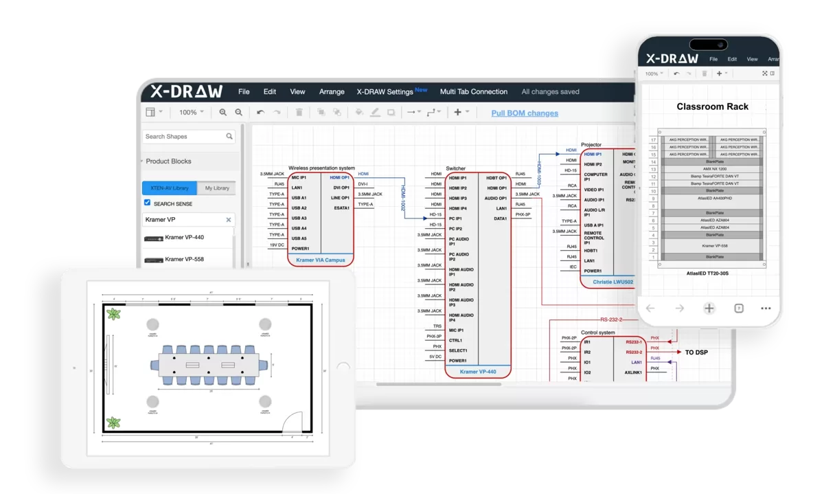
Key Features
Core Rack Planning Capabilities:
AI-assisted equipment selection with intelligent recommendations
90,000+ equipment database with daily manufacturer updates
Automated RU calculations with thermal, weight, and power analysis
Real-time 3D visualization with front/rear elevation views
Advanced cable management planning with pathway visualization
Thermal modeling using CFD (Computational Fluid Dynamics) simulation
Interactive drag-and-drop interface with collision detection
Advanced Features:
Multi-rack projects with synchronized planning across facilities
Signal flow diagrams automatically generated from rack designs
Integration with CAD/BIM platforms (AutoCAD, Revit)
Asset tracking and lifecycle management
Project templates for common configurations
Mobile field apps for installation verification
AR visualization for client walkthroughs
Version control with complete revision history
Collaboration Tools:
Cloud-based platform accessible anywhere
Multi-user editing with granular permissions
Real-time collaboration with instant updates
Client portals for remote reviews and approvals
Comment threads and markup tools
Video conferencing integration for design reviews
Documentation & Reporting:
Professional rack elevations (publication-quality)
Automated BOM generation with vendor pricing integration
Equipment schedules with complete specifications
Installation instructions with step-by-step procedures
As-built documentation from field updates
Export formats: PDF, DWG, DXF, CSV, JSON
Integration Ecosystem:
Project management software synchronization
Accounting systems for financial tracking
Procurement platforms for automated ordering
Facility management systems for asset data
Manufacturer configurators for equipment validation
Pros
✅ Unmatched equipment library with 90,000+ verified devices (largest in industry) ✅ Superior AI features reduce design time by 75% with intelligent suggestions ✅ Best-in-class thermal analysis prevents overheating issues before installation ✅ Exceptional customer support including dedicated account managers for enterprise clients ✅ Comprehensive training program with certification paths for professional development ✅ Regular feature updates (monthly releases) with user-requested enhancements ✅ Intuitive interface despite advanced capabilities – 1-week typical proficiency ✅ Mobile field apps enable real-time updates during installation ✅ Strongest collaboration features for distributed teams and client communication ✅ Flexible licensing from individual to enterprise with concurrent user options ✅ Outstanding ROI typically achieved within first 5-10 projects
Cons
❌ Premium pricing ($3,600-$6,000/year per user in 2026) – highest in category ❌ Requires reliable internet for full functionality (limited offline mode) ❌ Advanced features require training investment (2-4 weeks for mastery) ❌ May be excessive for very small firms doing simple installations exclusively ❌ Learning curve steeper than basic tools for advanced 3D modeling ❌ Equipment database bias toward North American manufacturers (though constantly expanding)
Best For
X-DRAW is the ideal choice for:
Professional AV integration firms with 5+ designers handling multiple concurrent projects
Design consultants requiring client presentation and collaboration tools
Enterprise system designers managing complex, multi-rack installations
Broadcast facilities and production companies with precision requirements
Teams prioritizing accuracy and willing to invest in training
Organizations seeking competitive advantage through advanced technology
Projects with 20+ rack units or distributed multi-room systems
Integrators billing $1M+ annually where software cost is negligible relative to revenue
Not ideal for:
Occasional installers with 1-2 simple projects annually
Very small projects consistently under 10U
Organizations without reliable high-speed internet
Teams unwilling to invest in proper training
Firms primarily doing residential work without commercial clients

D-Tools System Integrator (SI)
Strong alternative emphasizing business management alongside design.
Introduction
D-Tools SI combines project management, CRM, and rack design in unified platform, making it popular among full-service integrators who prioritize business operations alongside technical design.
Key Strengths
End-to-end workflow from lead to closeout
Integrated CRM and sales tools
Labor estimation and project tracking
Strong financial reporting
Good equipment library (60,000+ items)
Limitations
Thermal analysis less sophisticated than X-DRAW
Collaboration features more basic
Learning curve steep due to breadth of features
Interface feels dated compared to newer platforms
Best For
Integration firms prioritizing business management over advanced design features; companies wanting all-in-one solution for operations and technical work.
Pricing
$2,400-$4,500/year per user (2026 rates)
Stardraw Design 7
CAD-focused platform for detailed technical drawings.
Introduction
Stardraw excels at schematic creation and documentation, appealing to designers who prioritize drawing quality over automation.
Key Strengths
Exceptional drafting tools for precise technical drawings
Strong architectural integration for building plans
Detailed cable management documentation capabilities
Symbol libraries for all disciplines (AV, electrical, data)
Limitations
Less automation than AI-driven platforms
Manual calculations required for many planning tasks
Steeper learning curve for non-CAD users
Collaboration features limited
Best For
CAD-proficient designers requiring extensive documentation for construction projects; firms with architectural integration needs.
Pricing
$1,800-$3,200/year per user
AutoCAD with AV Add-ons
Generic CAD platform customized with industry plugins.
Strengths
Industry-standard file formats
Extensive customization possible
Integration with existing CAD workflows
Powerful general drafting capabilities
Limitations
Requires separate equipment libraries and calculation tools
No AV-specific automation
Manual thermal and power calculations
Expensive for features mostly unused in AV work
Best For
Firms already using AutoCAD for other disciplines; projects requiring architectural coordination in native AutoCAD.
Pricing
$1,775/year subscription (AutoCAD) + $500-$1,500 for AV plugins
Visio with AV Templates
Basic diagramming for simple projects.
Strengths
Low cost ($20/month Microsoft 365)
Easy learning curve
Wide adoption for business use
Good for conceptual diagrams
Limitations
No automation or calculations
Limited 3D capabilities
No equipment database
Manual everything
Best For
Very small projects, conceptual planning only, firms on extreme budgets.
Software Selection Guide
Choose based on your organization's priorities:
Priority | Recommended Software |
Best overall (no budget constraints) | X-DRAW |
Business management integration | D-Tools SI |
Technical drawing quality | Stardraw Design 7 |
Architectural coordination | AutoCAD + AV plugins |
Budget-conscious | D-Tools Cloud (lighter version) |
Simple projects only | Rack Builder (free online) |
Decision Factors: |
Project complexity: Complex projects justify advanced tools
Team size: Larger teams benefit most from collaboration features
Budget: Calculate ROI based on project volume
Existing workflows: Integration with current systems matters
Support needs: Consider training and support quality
Frequently Asked Questions
Q: How much rack space should I reserve for future expansion?
Reserve 20-30% spare capacity minimum. Corporate environments typically need 25-30%, educational facilities 35-40%, and tightly controlled broadcast facilities can use 15-20%. Never use 100% of available space in initial design.
Q: What's the difference between equipment rack space and usable rack space?
Total rack space is the nominal height (e.g., 42U). Usable space is typically 2-4U less due to structural supports, mounting constraints, and cable entry points. Plan using 38-40U available in a standard 42U rack.
Q: How do I calculate thermal spacing requirements?
Classify equipment by heat output: Low (<200 BTU/hr) needs 0U spacing; Moderate (200-500 BTU/hr) needs 1U above; High (>500 BTU/hr) needs 2U above and 1U below. Use manufacturer specs or calculate BTUs from watts (1W ≈ 3.41 BTU/hr).
Q: Should I use vertical or horizontal PDUs?
Vertical PDUs (0U) save rack space but reduce cable management area and may interfere with side-by-side rack placement. Horizontal PDUs (1-2U) consume equipment space but provide cleaner cable routing. Choose based on available space and cable density.
Q: What rack depth do I need for audio, video, and network equipment?
Most AV equipment fits in 24-30 inch depth racks. Measure your deepest device including rear connectors (add 4-6 inches to equipment depth), then select next standard size. Deep racks (30-36") required for IT servers or large power amplifiers.
Q: Can I mount power amplifiers at the top of racks?
No – mount heavy equipment (amplifiers, UPS units) in the bottom 30% of racks for stability. Top-heavy configurations create tipping hazards and potential equipment damage. Calculate center of gravity to ensure safe weight distribution.
Q: How often should I use cable management in racks?
Install horizontal cable managers every 6-8 rack units of equipment, or allocate 10-15% of total rack height for cable management. High-density installations may require managers every 4-6U for adequate organization.
Conclusion
Mastering AV rack planning through systematic space calculation for audio, video, and network equipment represents a fundamental competency for professional AV integrators and system designers. Understanding Audio Visual (AV) rack units and applying proven planning methodologies ensures installations that meet functional requirements, thermal management needs, and future scalability demands while staying within budget constraints.
The evolution from manual calculations and hand-drawn elevations to AI-powered design platforms has transformed rack planning from a tedious, error-prone process into a streamlined workflow that delivers superior results in dramatically less time. Modern software tools like X-DRAW don't just automate math – they enable intelligent decision-making, facilitate team collaboration, improve client communication, and generate comprehensive documentation that guides successful installations.
As AV systems continue growing more complex with converged AV/IT networks, cloud connectivity, and AI-enhanced processing, the importance of precise rack planning only intensifies. Professional integrators who invest in mastering calculation methodologies, understanding equipment-specific requirements, implementing proper cable management, and leveraging advanced design software position themselves for competitive advantage in an increasingly demanding marketplace.
Whether you're planning a simple 12U huddle space rack or a complex multi-rack broadcast facility, the principles remain consistent: account for all equipment accurately, provide adequate spacing for thermals and cables, plan for inevitable future growth, validate calculations thoroughly, and document everything professionally. By following the systematic approaches outlined in this guide and utilizing appropriate design tools, AV professionals can consistently deliver reliable installations that exceed client expectations while maintaining healthy profit margins and building reputations for technical excellence.
The time invested in proper rack planning – whether in training, software tools, or design process refinement – pays dividends throughout every project phase, from initial proposals through final commissioning and ongoing system support, ultimately defining the difference between adequate installations and truly exceptional AV systems.