How to Create a Schematic in Under 10 Minutes
This is where schematic drawing software comes in. Modern schematic diagram programs make it fast and easy to create professional-grade schematics in a matter of minutes. They offer an array of powerful features like component libraries, auto-routing, design rule checks, and automated bill of materials generation that dramatically speed up the design process.
So let's dive in and discover how you can create a polished, professional schematic in under 10 minutes!
The Importance of Schematic Drawing Software
Before we get into the nuts and bolts of actually creating a schematic, it's worth taking a moment to appreciate the critical role that schematic drawing software plays in the modern design workflow.
Today's schematic diagram programs have revolutionized the way engineers design circuits. They provide a digital canvas that is far more powerful and flexible than pen and paper. With just a few clicks, you can place components, draw wires, and add annotations. Intelligent features like auto-routing and design rule checks help prevent common errors and ensure your schematic adheres to industry standards.
Perhaps most importantly, schematic diagram programs create a digital thread that connects the schematic to other phases of the design process. The schematic serves as the foundation for PCB layout, component procurement, manufacturing, and testing. By starting with an accurate, well-organized schematic, you ensure a smooth and efficient transition to these downstream activities.
So in short, schematic drawing software is an indispensable tool for the modern engineer. It accelerates design cycles, improves accuracy, enables collaboration, and forms the bedrock of a successful project.
Now let's look at how you can harness its power to create a schematic in record time!
Step 1: Choose Your Schematic Drawing Software
However, for professional work or more complex designs, a commercial schematic drawing software package is usually a better choice. Industry-standard programs like Altium Designer, OrCAD Capture, or Autodesk EAGLE offer advanced capabilities such as:
- Extensive component libraries with detailed simulation models
- Intelligent auto-routing and connection management
- Automated design rule checks and error detection
- Integration with PCB layout and mechanical CAD tools
- Robust documentation and reporting features
When evaluating schematic diagram programs, also consider factors like ease of use, quality of technical support, licensing costs, and compatibility with your existing design tools and workflows.
Step 2: Create a New Project and Set Up Your Workspace
With your schematic drawing software selected, you're ready to start a new project. The exact steps will vary depending on your specific program, but the general process is similar.
Begin by launching the software and creating a new project or schematic document. Give the project a descriptive name and choose a location to save it. Some programs will prompt you to select a template or set up project-wide properties like design rules and libraries at this stage.
The key interface elements to locate are:
- Component library panel: This is where you'll select the symbols for resistors, capacitors, ICs, and other parts to place in your schematic.
- Wiring tools: Look for buttons or menu items that allow you to draw wires and buses to connect components.
- Annotation and text tools: You'll need these to add labels, values, notes, and other information to your schematic.
- Navigation controls: Find the zoom and pan options to move around your schematic as it grows in size and complexity.
- Design rule check and error navigation: Locate the tools that let you verify your schematic against design rules and quickly jump to any errors or warnings.
Take a few minutes to explore and experiment with the interface. Rearrange panels, try out keyboard shortcuts, and customize toolbars to suit your workflow. A well-organized workspace will help you work efficiently as you dive into drawing your schematic.
Step 3: Place and Connect Components
Now it's time to start placing components in your schematic. This is where the real power of schematic drawing software shines compared to manual drafting.
To place a component, simply locate it in the library panel and click to place it in the schematic editing window. You can usually search for components by name, description, or part number to quickly find what you need.
After placing several components, you'll want to start wiring them together. Use the wiring tool to draw connections between component pins. Many schematic drawing software packages will automatically snap wires to pins and detect connection points.
As you work, take advantage of your schematic diagram program's auto-routing and connection management features. These tools can automatically draw wires between pins based on signal names or net labels, saving you time and ensuring correct connectivity.
Step 4: Annotate and Document Your Schematic
For ICs and other complex components, add pin numbers or signal names to each pin. This clarifies the function of each connection and helps prevent wiring errors.
Many schematic diagram programs also allow you to attach external files like datasheets, simulation models, or manufacturing instructions to individual components or to the overall schematic. Take advantage of this capability to create a comprehensive documentation package.
Regularly run design rule checks and correct any errors or warnings. These automated checks can catch common issues like unconnected pins, missing power connections, or incorrect component values.
Step 5: Generate Outputs and Reports
- Bill of Materials (BOM): A list of all the components used in the design, with quantities, part numbers, and supplier information. The BOM is essential for procurement and cost estimation.
- Net list: A machine-readable description of the circuit's connectivity, used as an input for PCB layout and simulation tools.
- Cross-reference reports: Tables that map between reference designators, component values, and manufacturer part numbers, useful for debugging and assembly.
- Design rule check reports: A summary of any errors or warnings found by the automated design checks, with links to the affected components or nets in the schematic.
To generate these outputs, look for commands like "Generate BOM" or "Export Net list" in your schematic diagram program's menus. You may need to configure options like file format, included columns, or output directory.
Some advanced schematic diagram programs can even generate interactive HTML versions of the schematic with cross-probing and navigation features. These allow collaborators to explore the design without needing access to the original schematic file.
Why XTEN-AV X-DRAW Is the Best Schematic Drawing Software for AV Professionals and How It Create Schematics In 10 Minutes
For professionals working on AV system designs, a generic schematic drawing software package may not be the best fit. AV systems have unique requirements and design conventions that benefit from a specialized toolset.
1. AI-Powered Design Automation
For example, you could specify that you're designing a conference room system with a certain number of displays, microphones, and speakers. X-DRAW's AI engine will then propose an initial schematic layout with appropriate components and signal routing.
Of course, the AI-generated schematic is just a starting point. You can then refine and customize the design to suit the specific needs of the project. But by leveraging AI to handle much of the routine work, X-DRAW frees up your time to focus on the creative and strategic aspects of system design.
2. Manufacturer Product Library Integration
Another area where X-DRAW excels is its integration with manufacturer product libraries. The software includes an extensive and constantly updated database of AV components from all the leading brands like Crestron, Extron, QSC, Biamp, and more.
- Physical properties and dimensions
- Electrical specifications and signal types
- Connector pinouts and wiring details
- Symbols and graphics for schematics and rack layouts
- Links to manufacturer datasheets and manuals
Having this information at your fingertips streamlines the design process and ensures your schematics accurately represent the real-world components. You can quickly search for and place products based on their capabilities, without needing to manually create symbols or look up specifications.
3. Auto-Routing & Connection Management
X-DRAW streamlines this process with its intelligent auto-routing and connection management features. The software understands the signal types and connector compatibilities of different AV components and can automatically draw the appropriate connections between them.
This auto-routing capability is a huge productivity booster, especially for large and complex systems. It eliminates the tedious work of manually drawing and labeling every wire, while also reducing the risk of errors or omissions.
4. Schematic + Signal Flow Diagrams
Signal flow diagrams are a valuable tool for AV system design, as they provide a high-level overview of how the system functions without getting bogged down in wiring details. They're especially useful for communicating the design intent to stakeholders who may not be familiar with reading schematics.
You can also create rack elevation diagrams that show the physical layout of equipment in the AV racks. X-DRAW will automatically populate the rack diagrams with the components from the schematic, using the manufacturer-specific 2D or 3D models.
5. Auto-Generated BOMs and Proposals
X-DRAW automates this process by dynamically generating BOMs, cable schedules, and other project documents directly from the system design. As you add, remove, or modify components in the schematic, the associated documents update in real-time.
- Manufacturer and model number
- Description and specifications
- Quantity required
- Unit and extended pricing
- Supplier and availability information
X-DRAW can output BOMs in a variety of formats, including CSV, Excel, and PDF, for easy integration with your existing procurement and project management workflows. You can also customize the BOM templates to match your company's branding and style guidelines.
In addition to BOMs, X-DRAW can generate professional-quality proposals and system documentation packages.
The proposals are generated directly from your system designs, ensuring consistency and accuracy across all project documentation. You can easily customize proposal templates with your company branding, cover pages, terms and conditions, and more.
6. Cloud-Based Collaboration
X-DRAW's real-time sync means changes made by one user are instantly visible to everyone else. No more emailing files back and forth or wondering if you have the latest version. The platform also includes robust version control, so you can easily track changes and revert to previous designs if needed.
7. Standards Compliance
The software's built-in symbol libraries and design methodologies align with industry conventions for signal flow, device representation, and documentation. This helps ensure your designs are clear, consistent, and technically sound.
By building standards compliance into the core of the software, X-DRAW helps AV professionals work more efficiently while upholding the highest levels of quality and professionalism.
8. Analytics and Revision Tracking
In addition to its powerful design capabilities, X-DRAW also offers valuable insights and analytics to help AV teams work smarter. The software automatically tracks key project metrics like design time, component usage, and revision history.
Project managers can see at a glance how much time was spent on each phase of the design, helping to identify bottlenecks and optimize resource allocation. Component-level analytics show which products are used most frequently across projects, informing purchasing decisions and standardization efforts.
By leveraging X-DRAW's analytics and tracking features, AV teams can gain deep visibility into their projects and make data-driven decisions to boost productivity and profitability.
Frequently Asked Questions about AV Schematic Design
What is the difference between a schematic and a wiring diagram?
How detailed should an AV schematic be?
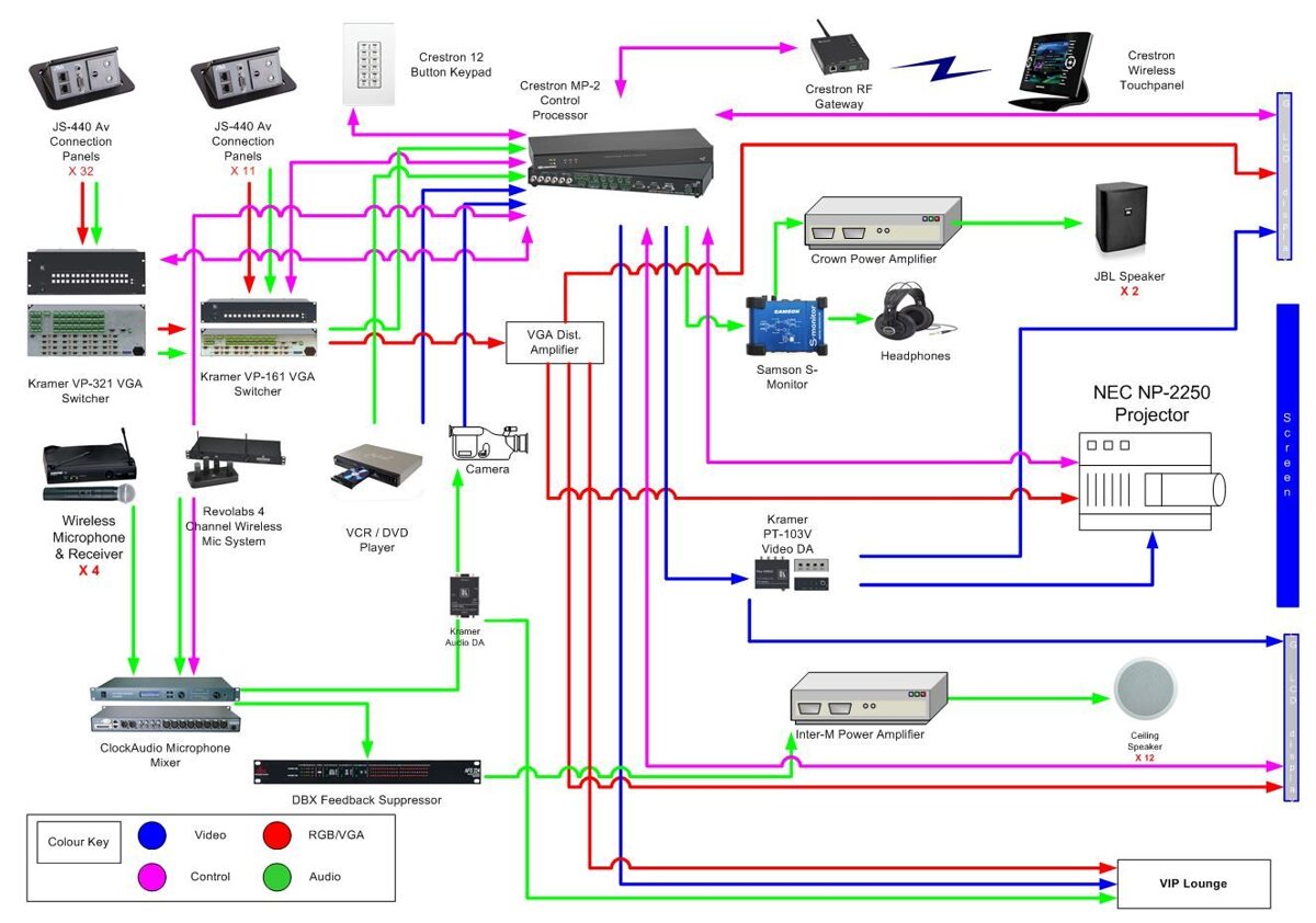
What are the key components to include in an AV schematic?
- Sources like computers, media players, and microphones
- Signal processing and switching equipment like mixers and matrix switchers
- Amplifiers and speakers
- Video displays and projectors
- Control systems and user interfaces
- Cabling and connectors
How can I make my AV schematics look more professional?
Using AV-specific software like X-DRAW is a great start, as it includes professional templates, symbols, and automation features. Beyond that, focus on consistency in your layout, labeling, and formatting. Include a title block with key project info, and consider adding your company logo for branding.
Can I generate an equipment list from my AV schematic?
Yes, one of the big advantages of using intelligent schematic design software is the ability to automatically generate bills of materials (BOMs) from your drawings. X-DRAW makes this easy - as you add components to your schematic, they are instantly reflected in an exportable BOM, complete with quantities, part numbers, and pricing.
How can I share my AV schematics with clients or colleagues?
X-DRAW's cloud-based platform is ideal for collaboration. You can invite clients and team members to view and comment on your schematics in real-time, without needing to install any software. The platform also supports exporting schematics to universal formats like PDF for easy sharing and markup.
Case Studies: AV Companies Succeeding with X-DRAW
Case Study 1: Streamlining Design at a University AV Department
The AV services team at a large public university was struggling to keep up with a growing volume of classroom technology projects. Each design was taking hours to create in generic diagramming software, and inconsistencies between drawings were causing confusion for installers.
The X-DRAW platform also made it easy for the team to collaborate with faculty stakeholders on classroom designs. Cloud-based access and an intuitive interface meant professors could provide input directly on the schematics, without the back-and-forth of emails and meetings.
Case Study 2: Winning More Bids at an AV Integration Firm
Implementing X-DRAW gave the integration firm a powerful advantage in the bidding process. Instead of bland equipment lists, they were now able to quickly generate professional-grade proposals including detailed system schematics and rack visualizations. The visual impact helped clients understand the value of the proposed solution and made the integrator stand out from other bids.
On won projects, X-DRAW helped the integrator get systems installed faster and with fewer errors. Technicians had clear, industry-standard drawings to work from, and any changes in the field could be reflected in the design in real-time. Faster, cleaner installs meant happier clients and healthier margins.
Conclusion
By standardizing on an industry-leading platform, you'll be able to create schematics faster, win more bids, and deliver successful projects with ease. You'll spend less time fighting with software and more time designing amazing AV experiences.
Sign up today and see how X-DRAW can help you create better schematics in a fraction of the time. Your clients, your team, and your bottom line will thank you!