How to Organize AV Equipment in a Wall Mount Rack for Maximum Efficiency
Efficient equipment organization within a wall mount Audio Visual (AV) rack directly determines system reliability, maintenance efficiency, thermal performance, and overall installation quality. Poor rack organization creates cascading problems—from equipment overheating and cable management chaos to difficult troubleshooting and costly service callbacks. Professional AV integrators understand that strategic equipment placement, logical device sequencing, and systematic cable routing separate exceptional installations from mediocre ones.
Beyond basic equipment mounting, knowing how to mount Audio Visual (AV) rack on wall with optimal device organization requires understanding thermal dynamics, signal integrity, weight distribution, cable management principles, and maintenance accessibility. Properly organized racks enable technicians to quickly identify equipment, trace signal paths, diagnose issues, and perform system upgrades without disrupting adjacent devices—competencies essential for competitive AV integration firms.
This comprehensive guide provides AV integrators, system designers, and installation technicians with proven methodologies for organizing AV equipment within wall mount racks. From fundamental equipment sequencing principles through advanced cable management strategies and thermal optimization, these practical techniques ensure your rack deployments achieve maximum efficiency, reliability, and professional presentation.
Key Takeaways
Equipment organization in wall mount racks directly impacts system reliability, thermal performance, maintenance accessibility, and troubleshooting efficiency
Strategic equipment placement follows the principle: heavy devices bottom, heat-generating equipment near bottom, frequently accessed devices at optimal heights
Logical equipment sequencing based on signal flow reduces cable complexity and improves installation clarity
Weight distribution requires positioning heaviest equipment near rack bottom to minimize wall stress and prevent mounting failures
Thermal management demands adequate spacing (minimum 1U) between heat-generating devices and proper airflow planning
Cable organization begins with infrastructure installation before equipment mounting, not as an afterthought
Power distribution should be planned for balanced electrical loads, proper circuit utilization, and future expansion
Accessibility planning ensures frequently maintained equipment occupies positions allowing service without disturbing other devices
Labeling systems for both equipment and cables accelerate troubleshooting and reduce maintenance time
Modern AV design software like XTEN-AV's X-DRAW automates optimal equipment sequencing and rack organization planning
Documentation including detailed rack elevation diagrams and equipment inventories is essential for long-term system management
Proper organization reduces installation time, minimizes service callbacks, and improves client satisfaction
What Is a Wall Mount AV Rack?
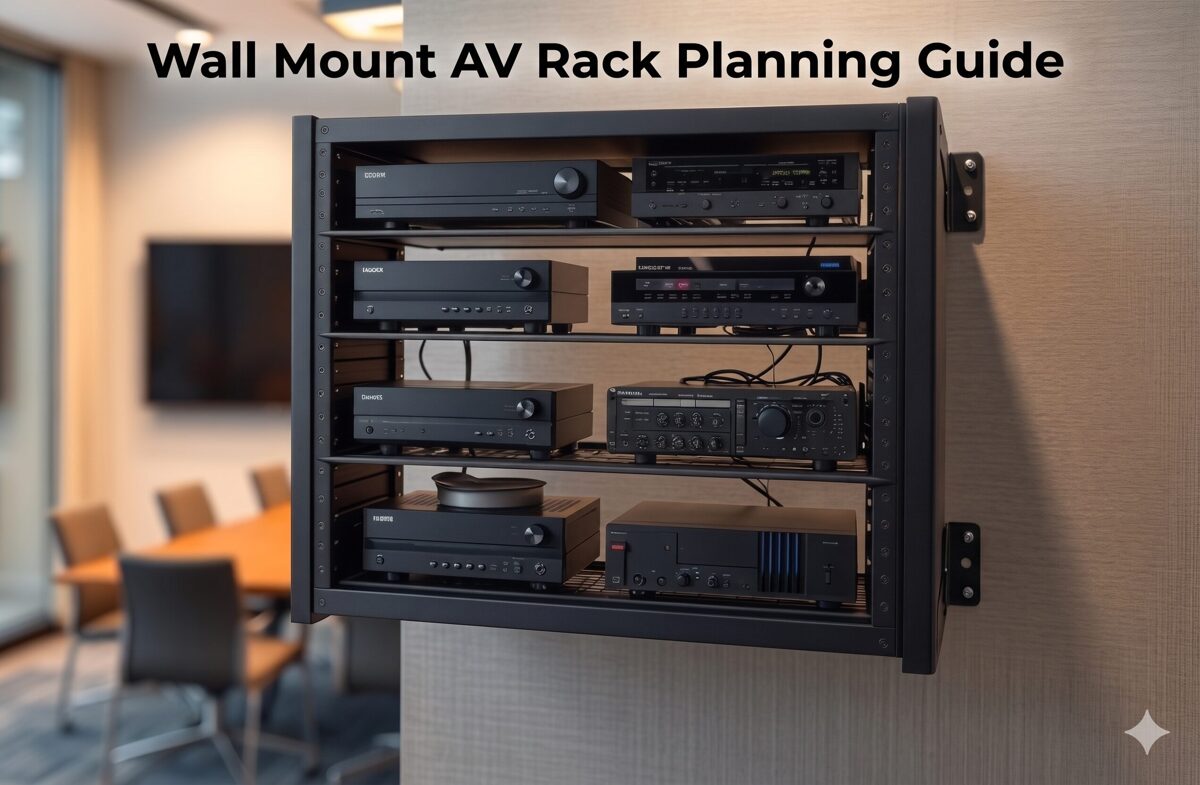
A wall mount AV rack is a vertical equipment enclosure or mounting framework that attaches securely to wall surfaces while providing standardized mounting positions for rack-mountable AV equipment. These racks serve as the centralized housing for video processors, audio equipment, network switches, control systems, signal distribution, and power management devices.
Technical Foundation
Wall mount racks adhere to industry standards:
Rack Unit (RU or U) measurement: Each unit represents 1.75 inches (44.45mm) of vertical space
EIA-310-D or IEC 60297 compliance: Standardized mounting hole patterns and spacing
19-inch width: Universal standard between mounting rails ensuring equipment compatibility
Typical capacity: 6U-22U for wall-mounted applications (larger sizes become floor standing racks)
Depth variations: 12-24 inches accommodating different equipment dimensions
Organizational Components
Well-designed wall mount racks include:
Mounting rails: Vertical rails with threaded holes for equipment attachment
Cable management: Vertical cable managers, horizontal organizers, cable entry/exit provisions
Power distribution: Mounting locations for PDUs and electrical infrastructure
Ventilation: Perforated panels, fan mounting positions, airflow channels
Blank panels: Filler panels maintaining airflow control and professional appearance
Enclosure options: Open frame, vented enclosures, or solid enclosures based on security/cooling needs
Equipment Organization Context
Effective rack organization transforms these components into efficient AV system platforms by strategically positioning equipment to optimize thermal performance, cable management, maintenance access, and system reliability.
Why Proper AV Rack Organization Matters
Strategic equipment organization within wall mount racks impacts multiple critical factors beyond simple device mounting.
1. System Reliability and Equipment Longevity
Proper organization directly affects equipment lifespan:
Thermal optimization: Correct equipment spacing and heat distribution prevent thermal failures and extend component life
Vibration isolation: Separating mechanical equipment (fans, hard drives) from sensitive devices reduces vibration-induced failures
Electrical interference: Strategic device separation minimizes electromagnetic interference (EMI) affecting signal quality
Weight distribution: Proper load management prevents mounting stress and rack failures
2. Maintenance Efficiency and Reduced Downtime
Organized racks accelerate service workflows:
Quick equipment identification: Logical device placement enables technicians to rapidly locate specific components
Accessible connections: Well-planned equipment positioning allows cable access without removing multiple devices
Efficient troubleshooting: Clear signal flow organization helps technicians trace paths and diagnose issues
Reduced service time: Organized installations decrease maintenance duration and associated costs
3. Cable Management and Signal Integrity
Strategic equipment sequencing simplifies cable routing:
Shorter cable runs: Positioning related equipment adjacently reduces cable lengths and signal loss
Organized pathways: Logical equipment placement creates natural cable routing patterns
Reduced cable congestion: Proper device spacing prevents cable overcrowding and tangling
Signal quality: Appropriate equipment separation (e.g., power from signal devices) maintains signal integrity
4. Thermal Management and Cooling Efficiency
Equipment organization determines thermal performance:
Heat stratification: Positioning heat-generating equipment appropriately leverages natural heat rise
Airflow optimization: Strategic device placement creates effective cooling paths through rack
Hotspot prevention: Proper equipment spacing prevents localized heat accumulation
Cooling efficiency: Organized racks reduce cooling fan requirements and energy consumption
5. Professional Appearance and Client Confidence
Well-organized racks demonstrate installation quality:
Visual impact: Clean, organized equipment presentation impresses clients and builds confidence
Brand differentiation: Professional rack organization distinguishes quality integrators from competitors
Documentation quality: Organized systems photograph better for portfolio and marketing materials
Client perception: Neat installations suggest attention to detail and system reliability
6. Future Expansion and System Scalability
Thoughtful organization accommodates growth:
Reserved space: Planned equipment positioning leaves strategic rack units available for additions
Flexible routing: Organized cable infrastructure enables easy equipment additions
Power availability: Strategic PDU placement ensures outlets remain accessible for new devices
Documentation accuracy: Well-organized systems are easier to document, facilitating future modifications
7. Installation Efficiency and Cost Reduction
Strategic pre-planning of equipment organization reduces installation costs:
Faster deployment: Clear equipment placement plans accelerate installation workflows
Reduced errors: Pre-planned organization minimizes mounting mistakes requiring rework
Material optimization: Proper device sequencing reduces cable and hardware waste
Labor savings: Organized approaches reduce installation hours and associated costs
Common Problems Caused by Poor Rack Organization
Understanding failure modes helps AV integrators avoid costly mistakes and improve installation practices.
1. Thermal Failures and Equipment Overheating
Problem: Heat-generating equipment clustered together or positioned at rack top without adequate ventilation.
Consequences:
Equipment overheating causing thermal shutdowns during operation
Premature component failures reducing equipment lifespan
Intermittent system performance issues difficult to diagnose
Warranty voiding due to operating outside temperature specifications
Example: Three network switches mounted consecutively at rack top without spacing, each generating 150W, creating localized hotspot exceeding 140°F.
2. Cable Management Chaos
Problem: Equipment positioned without considering cable routing, creating cable congestion and disorganization.
Consequences:
Tangled cables making troubleshooting difficult and time-consuming
Cable stress at connection points causing intermittent failures
Difficulty tracing signal paths during diagnostics
Unprofessional appearance damaging client confidence
Airflow obstruction from cable masses blocking ventilation
Example: Video matrix switcher at rack bottom with displays connected throughout facility, requiring cables to run entire rack height through congested vertical managers.
3. Maintenance Accessibility Issues
Problem: Frequently serviced equipment positioned in locations requiring extensive disassembly to access.
Consequences:
Extended service times increasing maintenance costs
Higher risk of cable disconnection when moving equipment for access
Technician frustration leading to rushed work and potential errors
Increased system downtime during maintenance windows
Example: Media player requiring weekly content updates mounted behind cable management at rack top, necessitating ladder and cable routing disruption for every update.
4. Structural and Weight Distribution Problems
Problem: Heavy equipment concentrated at rack top or unevenly distributed side-to-side.
Consequences:
Excessive wall stress at upper mounting points risking failure
Rack tipping hazard during door opening or equipment access
Potential mounting bracket failures under unbalanced loads
Equipment damage if rack stability compromised
Example: 40-lb amplifier and 35-lb UPS mounted at rack top with lightweight switches below, creating top-heavy configuration stressing wall anchors.
5. Power Distribution Inefficiencies
Problem: PDU positioned inconveniently or power cords routed chaotically without planning.
Consequences:
Power cord congestion blocking equipment access and airflow
Excessive cord lengths creating cable management challenges
Difficult power cord tracing during troubleshooting
PDU outlet accessibility blocked by cable masses
Example: PDU mounted at rack top with all equipment below, requiring long power cords running full rack height, consuming cable manager space needed for signal cables.
6. Signal Flow Confusion
Problem: Equipment positioned randomly without following logical signal paths.
Consequences:
Difficult system understanding for maintenance technicians
Complex troubleshooting requiring extensive cable tracing
Higher risk of mis-wiring during installations or modifications
Poor documentation accuracy due to non-intuitive equipment layout
Example: Video source at rack bottom, switcher at top, distribution amplifier in middle, creating confusing signal flow and excessive cable crossings.
7. Future Expansion Limitations
Problem: Equipment densely packed without reserved rack space for anticipated growth.
Consequences:
Expensive rack replacement required for modest equipment additions
Complex equipment rearrangement to accommodate new devices
Temporary installations compromising system organization
Client frustration with limited scalability
Example: 12U rack filled completely during initial installation, requiring expensive rack replacement and complete system reinstallation when client adds video recording device six months later.
8. Documentation Discrepancies
Problem: Equipment installed differently than documented rack elevation diagrams.
Consequences:
Documentation becomes unreliable for future maintenance
Technicians waste time locating equipment not matching diagrams
System modifications based on incorrect documentation create errors
Knowledge loss when original installers unavailable
Example: Rack elevation shows equipment sequence, but installer reverses positions during deployment without updating documentation, confusing future service teams.
Step-by-Step Guide to Organizing AV Equipment in a Wall Mount Rack
This comprehensive methodology ensures optimal equipment organization from planning through deployment.
Phase 1: Pre-Planning and Equipment Assessment
Step 1: Create Complete Equipment Inventory
Develop detailed equipment list with critical specifications:
Essential Information:
Device name and model number
Rack unit height (RU) requirement
Equipment depth (front-to-rear dimension)
Weight (for load distribution planning)
Power consumption (watts) and heat generation (BTU/hr)
Connection requirements (input/output ports, quantity and type)
Cooling requirements (passive vs. active cooling needs)
Maintenance frequency (daily, weekly, monthly, rarely)
Example Inventory:
Equipment | RU | Depth | Weight | Power | Heat | Maintenance |
Video Matrix | 2U | 18" | 25 lbs | 150W | 512 BTU/hr | Rare |
Network Switch | 1U | 12" | 8 lbs | 75W | 256 BTU/hr | Occasional |
Control Processor | 1U | 10" | 5 lbs | 25W | 85 BTU/hr | Occasional |
Step 2: Analyze Signal Flow Paths
Map signal routing through equipment chain:
Identify all signal sources (cameras, computers, media players)
Trace signal path through processing equipment (switchers, scalers, distribution amplifiers)
Map signal destinations (displays, speakers, recording devices)
Document control system connections
Note network infrastructure requirements
Signal Flow Example:
Sources → Video Matrix Switcher → Distribution Amplifier → Displays
Control: Touch Panel → Control Processor → Serial/IP Control → Equipment
Step 3: Assess Thermal Characteristics
Categorize equipment by heat generation:
High-Heat Equipment (>100W/device):
Amplifiers
High-density network switches
Video processors with multiple outputs
Media servers and computers
Medium-Heat Equipment (50-100W/device):
Video switchers
Matrix switchers
Standard network switches
Power supplies
Low-Heat Equipment (<50W/device):
Control processors
Cable management panels
Patch panels
Distribution amplifiers
Step 4: Determine Maintenance Access Requirements
Classify equipment by service frequency:
Frequent Access (weekly or more):
Media players requiring content updates
Video sources with media insertion
Equipment with user-adjustable controls
Occasional Access (monthly or quarterly):
Network switches requiring port access
Control processors for programming updates
Equipment with firmware update needs
Rare Access (annual or less):
Video processors with stable configurations
Distribution equipment
Signal management devices
Phase 2: Strategic Equipment Sequencing
Step 5: Position Equipment by Weight Distribution
Organize devices vertically for optimal load management:
Bottom Section (Lower 1/3 of Rack):
Heaviest equipment (>20 lbs per device)
High-wattage amplifiers
UPS systems and power conditioning
Dense video processors
Middle Section (Center 1/3 of Rack):
Medium-weight equipment (10-20 lbs)
Network switches
Video switchers and matrices
Cable management panels
Top Section (Upper 1/3 of Rack):
Lightweight equipment (<10 lbs)
Control processors
Patch panels
Final cable management and blank panels
Weight Distribution Principle: Bottom-heavy configuration minimizes wall stress and prevents mounting failures.
Step 6: Sequence Equipment Following Signal Flow
Arrange devices in logical signal path order:
Option A: Top-to-Bottom Signal Flow
Sources at rack top
Processing equipment in middle
Distribution equipment at bottom
Advantage: Natural cable drop from sources through processing
Option B: Bottom-to-Top Signal Flow
Sources at rack bottom
Processing in middle
Distribution at top
Advantage: Sources accessible at lower heights
Best Practice: Choose approach minimizing cable length and complexity based on where signal sources physically connect (e.g., if sources connect from above rack, use top-to-bottom flow).
Step 7: Position Equipment by Thermal Characteristics
Organize for optimal heat management:
Heat Management Strategy:
Position highest-heat equipment near rack bottom (heat rises naturally)
Maintain minimum 1U spacing between high-heat devices
Alternate high-heat and low-heat equipment when possible
Reserve rack top area for cooling fan exhaust path
Install blank panels to direct airflow through equipment
Example Organization (12U Rack):
1-2U: Amplifier (high heat) at bottom
3U: Blank panel or cable manager (spacing)
4-5U: Video matrix (medium heat)
6-7U: Network switch (medium heat)
8U: Cable management (spacing)
9-10U: Control processor + patch panel (low heat)
11-12U: Blank panels (top ventilation space)
Step 8: Plan Equipment for Maintenance Accessibility
Position devices by service frequency:
Optimal Height Positioning (48-72 inches from floor = comfort zone):
Frequently accessed equipment at rack center (no ladder required)
Front-panel controls easily visible and reachable
Media insertion devices at convenient heights
Less Accessible Positions:
Rarely serviced equipment at rack bottom (below 48 inches)
Stable equipment at rack top (above 72 inches)
Equipment with remote management positioned for cable access priority
Step 9: Reserve Rack Space for Future Expansion
Strategically allocate unused rack units:
Expansion Planning:
Reserve 20-30% total rack capacity for growth
Position reserved space near related equipment (e.g., reserve 1-2U near video switching for additional input card)
Install blank panels in reserved positions maintaining airflow control
Document reserved space purpose in as-built drawings
Plan power and cooling capacity for future equipment
Phase 3: Create Detailed Rack Elevation Diagram
Step 10: Document Equipment Positions
Develop professional rack layout drawing:
Rack Elevation Components:
RU numbering (1U at bottom progressing upward)
Equipment names and model numbers at each position
Blank panel locations
Cable management panel positions
PDU location and type
Ventilation/cooling provisions
Documentation Tools:
Professional AV design software (XTEN-AV X-DRAW, Visio, AutoCAD)
Manual drafting with rack elevation templates
Spreadsheet-based rack planning tools
Step 11: Validate Organization Plan
Review equipment layout against criteria:
Validation Checklist:
☐ Weight distribution: Heaviest equipment at bottom
☐ Thermal management: Adequate spacing between high-heat devices
☐ Signal flow logic: Equipment sequence follows signal path
☐ Maintenance access: Frequently serviced equipment at optimal heights
☐ Cable routing: Equipment positions enable efficient cable management
☐ Future expansion: Reserved rack space for anticipated additions
☐ Power distribution: PDU position supports efficient power cord routing
☐ Total RU count: Equipment plus cable management fits within rack capacity
Phase 4: Equipment Installation Execution
Step 12: Install Cable Management Infrastructure First
Prepare cable routing before equipment mounting:
Install vertical cable managers on both rack sides
Pre-position horizontal cable organizers at planned locations
Mount cable entry/exit panels at rack top/bottom
Verify adequate cable routing depth behind equipment mounting area
Step 13: Mount Equipment Following Rack Elevation
Install devices systematically per documented plan:
Installation Sequence:
Begin with bottom-most equipment
Install each device at specified RU position
Verify level alignment before tightening mounting screws
Install blank panels between equipment as planned
Progress upward through rack completing all equipment mounting
Quality Checks During Mounting:
Confirm RU positions match elevation diagram
Verify equipment oriented correctly (front facing out)
Check adequate mounting screw engagement (minimum 3 threads)
Ensure no equipment interference or binding
Step 14: Install and Configure Power Distribution
Mount PDU and establish electrical infrastructure:
PDU Positioning Options:
Rear-mounted vertical: Behind equipment on rear mounting rail (saves front rack space)
Front-mounted vertical: Side position on front mounting rail (easy access but uses rack space)
Horizontal: Mounted in 1-2U rack space (good outlet visibility)
Best Practice: Rear-mounted vertical PDU on left or right side optimizes front rack space for equipment while enabling organized power cord routing.
Step 15: Route and Connect Signal Cables
Implement systematic cable routing following equipment organization:
Cable Installation Process:
Route video cables first (HDMI, DisplayPort, HDBaseT) following signal flow
Install audio cables maintaining 6-inch separation from power cables
Route network cables (Cat6/Cat6A) with proper bend radius
Connect control cables (RS-232, IR, relay, GPIO)
Dress cables through horizontal organizers between equipment layers
Create service loops in vertical managers for maintenance flexibility
Label all cables at both source and destination ends
Cable Routing by Equipment Section:
Equipment near rack bottom: Cables enter vertical managers at device level, route upward or downward to connections
Middle equipment: Cables route to adjacent devices through nearby horizontal organizers
Top equipment: Cables enter from top cable entry, route downward through vertical managers
How to Manage Cables Inside a Wall Mount AV Rack
Professional cable management is inseparable from effective equipment organization, creating the infrastructure supporting system reliability and maintenance efficiency.
Cable Management Principles
1. Cable Segregation by Type
Separate cables by function and characteristics:
Power Cables (Group 1):
AC power cords from equipment to PDU
Route through dedicated power cable path in vertical manager
Maintain minimum 6-inch separation from signal cables
High-Bandwidth Video Cables (Group 2):
HDMI, DisplayPort, SDI cables
Route through center section of vertical managers
Avoid tight bends (maintain 10x cable diameter bend radius)
Network and Data Cables (Group 3):
Cat6/Cat6A Ethernet cables
Fiber optic cables (special bend radius care)
Route through separate vertical manager section
Audio Cables (Group 4):
Balanced audio (XLR, TRS)
Analog audio (RCA, 3.5mm)
Separate from power cables to prevent noise interference
Control Cables (Group 5):
Low-voltage control (RS-232, RS-485)
IR, relay, GPIO
Can route with data cables but keep organized
2. Service Loop Implementation
Create maintenance flexibility through strategic cable slack:
Service Loop Best Practices:
Length: 12-18 inches excess for typical installations
Location: Store loops in vertical cable managers near equipment
Organization: Coil loops neatly, secure with velcro
Purpose: Enable equipment removal for servicing without cable disconnection
3. Cable Labeling Standards
Implement comprehensive identification system:
Label Format:
Source end: "SOURCE-DEVICE [PORT] → DEST-DEVICE [PORT]"
Destination end: Same label or inverse format
Example: "LAPTOP-HDMI-1 → MTX-IN3" (at source) / "MTX-IN3 ← LAPTOP-HDMI-1" (at destination)
Label Placement:
Within 6 inches of connector
Visible without moving cables
Oriented for easy reading
Secured to cable not connector
Label Tools:
Professional label printer (Brother P-Touch, DYMO)
Heat-shrink label tubes for small cables
Adhesive labels for larger cable bundles
Color-coded labels by cable type (optional)
Cable Management Installation Process
Step 1: Plan Cable Routes Before Installation
Map cable pathways before physical routing:
Identify source and destination for each cable
Determine optimal routing path through vertical managers
Calculate required cable lengths (actual path + service loop + 10% margin)
Plan bundle groupings (which cables route together)
Document cable routing plan in system documentation
Step 2: Route Cables Systematically
Install cables following organized approach:
Routing Sequence:
Power cables first (establish electrical infrastructure)
Video cables second (highest bandwidth, most routing critical)
Network cables third (medium bandwidth, moderate routing flexibility)
Audio cables fourth (avoid power cable proximity)
Control cables last (most flexible routing, lowest bandwidth)
Step 3: Dress and Secure Cable Bundles
Organize cables within management infrastructure:
Bundling Technique:
Group 4-8 related cables into bundles (avoid over-sized bundles)
Align cables parallel without twisting
Secure bundles with velcro wraps every 6-12 inches
Leave bundles slightly loose (avoid constricting cables)
Route bundles through vertical managers and horizontal organizers
Securing Best Practices:
Use velcro hook-and-loop wraps (reusable, non-damaging)
Avoid zip ties (permanent, can damage cables if over-tightened)
Never exceed manufacturer-specified bend radius
Maintain cable jacket integrity (no crimping or crushing)
Step 4: Create Organized Service Loops
Store excess cable systematically:
After connecting both ends, determine excess cable length
Form neat coil (4-6 inch diameter) with excess
Secure coil with velcro wrap
Store coil in vertical manager near equipment
Ensure coil doesn't block airflow or equipment access
Step 5: Implement Cable Strain Relief
Protect cable connections from stress:
Support cable weight within 12 inches of connector
Avoid cable hanging unsupported from connectors
Use horizontal organizers near equipment providing strain relief
Secure cables to vertical managers preventing connector pull
Advanced Cable Management Techniques
Color-Coded Cable System
Enhance cable identification through color:
Color Coding Scheme Example:
Blue cables: Video signals (HDMI, HDBaseT)
Yellow cables: Network/data (Cat6)
Red cables: Audio connections
Black cables: Power connections
White cables: Control signals
Implementation: Use colored cables or colored cable labels/boots indicating type.
Cable Combing
Create professional appearance:
Combing Technique:
After securing cable bundles, adjust individual cables within bundle
Align cables perfectly parallel
Space evenly within bundle
Verify labels visible
Fine-tune velcro wrap positions for neat appearance
Documentation Photography
Capture cable management for future reference:
Photograph rack before cable installation (clean equipment mounting)
Photograph cable routing during installation (capture routing paths)
Photograph completed rack from multiple angles (front, sides, rear)
Photograph cable labels and service loops
Store photos with system documentation
Airflow and Cooling Considerations for Wall Mount AV Racks
Thermal management is inseparable from equipment organization, directly determining system reliability and equipment longevity.
Understanding Thermal Dynamics in Wall Mount Racks
Heat Generation and Distribution
Equipment generates heat during operation:
Heat Sources:
Power supplies: Convert AC power to DC, generating heat
Processors: CPU/GPU chips in video processors, media servers
Amplifiers: Power amplification inherently inefficient, producing significant heat
Displays/Indicators: LEDs and displays generate modest heat
Transformers: Magnetic transformers in legacy equipment
Heat Behavior:
Heat rises naturally (convection)
Hot air accumulates at rack top without ventilation
Heat radiates to adjacent equipment
Enclosed racks trap heat without air circulation
Temperature Impact on Equipment
Excessive heat degrades equipment performance and reliability:
Temperature Effects:
Optimal operating range: Most AV equipment rated 32-104°F (0-40°C)
Reduced lifespan: Every 18°F (10°C) above optimal doubles failure rate
Thermal shutdowns: Equipment protects itself by shutting down at critical temperatures
Component degradation: Capacitors, semiconductors age faster at elevated temperatures
Thermal Management Strategies
1. Equipment Spacing for Airflow
Create airflow paths through rack:
Spacing Guidelines:
Minimum 1U between high-heat devices (>100W)
2U spacing between very high-heat equipment (>200W)
Blank panels fill unused space (direct airflow through equipment, not around it)
Equipment with side ventilation needs rack width clearance
Example Organization (Thermal Focus):
1-2U: Amplifier (150W) at bottom
3U: Blank panel (spacing + airflow control)
4-5U: Network switch (75W)
6U: Blank panel (spacing)
7-8U: Video processor (100W)
9-10U: Control processor (25W) + patch panel (0W)
11-12U: Blank panels (top exhaust space)
2. Positioning Heat-Generating Equipment
Strategic device placement by thermal output:
Bottom-Heavy Heat Distribution:
High-heat equipment at rack bottom (heat rises away naturally)
Medium-heat in middle section
Low-heat at top
Cooling fans at very top (exhaust heat from entire rack)
Benefits:
Natural convection assists cooling
Top equipment experiences lowest temperatures
Fan efficiency maximized by exhausting accumulated heat
3. Active Cooling Solutions
When passive ventilation insufficient:
Fan Installation:
Top-mounted exhaust fans: Most effective position (remove accumulated heat)
Bottom intake fans: Optional for high-heat racks (create positive airflow)
Thermostat control: Activate fans only when needed (reduce noise, energy)
Fan Specifications:
Adequate CFM (Cubic Feet per Minute) for rack volume and heat load
Low noise (typically <35dB for client-facing spaces)
1U rack mount configurations
Redundant fan arrays for reliability
Calculating Fan Requirements:
Sum total equipment power (watts)
Convert to heat (BTU/hr = Watts × 3.41)
Calculate CFM needed: CFM = (BTU/hr × 1.08) / (Temperature rise in °F)
Example: 500W equipment = 1,705 BTU/hr; Assuming 15°F temperature rise: CFM = (1,705 × 1.08) / 15 = 123 CFM required
4. Rack Enclosure Selection
Choose enclosure type supporting thermal requirements:
Open Frame Racks:
Maximum natural airflow (all sides open)
Best for high-heat installations in secure equipment rooms
No dust protection
Vented/Perforated Enclosure:
Good airflow (30-60% open area in doors/panels)
Reasonable dust protection
Security via lockable doors
Best balance for most applications
Solid Enclosure:
Minimal airflow (requires active cooling)
Maximum security and dust protection
Only suitable for low-heat equipment (<200W total) or with fan systems
5. Maintaining Clearances
Ensure adequate space around rack:
Clearance Requirements:
6-12 inches on all sides for air circulation
12 inches minimum above rack (heat exhaust)
Avoid rack installation in closed cabinets without ventilation
Position away from heat sources (windows, HVAC discharge, other equipment)
6. Cable Management Impact on Airflow
Prevent cable obstruction of cooling:
Airflow-Friendly Cable Management:
Route cables along rack sides in vertical managers (not through center)
Keep cable bundles compact (avoid sprawling cable masses)
Position service loops in vertical managers (not blocking equipment ventilation)
Use horizontal organizers above/below equipment (not blocking face ventilation)
Thermal Monitoring and Testing
Temperature Verification
Confirm adequate cooling post-installation:
Monitoring Methods:
Thermal camera: Visualize heat distribution across rack
Remote temperature sensors: Monitor critical zones continuously
Equipment built-in temperature reporting (SNMP, web interface)
Infrared thermometer: Spot-check equipment temperatures
Acceptable Temperatures:
Intake air: Below 77°F (25°C) ideal
Equipment surfaces: Below 95°F (35°C) desirable
Exhaust air: 10-20°F above intake acceptable
Alarm threshold: >104°F (40°C) requires cooling improvement
Thermal Load Documentation
Record thermal characteristics for future reference:
Documentation Elements:
Total power consumption by equipment
Calculated heat generation (BTU/hr)
Cooling solution implemented (passive vs. active)
Measured temperatures at key locations
Fan specifications if installed
Ambient temperature range in installation environment
How XTEN-AV's X-DRAW Simplifies Wall Mount AV Rack Organization
Modern AV system design demands intelligent planning tools that ensure optimal equipment organization before physical installation. XTEN-AV's X-DRAW platform represents a specialized AV design automation solution that transforms rack organization planning from manual trial-and-error into data-driven, optimized workflows.
Introduction to X-DRAW for Rack Organization
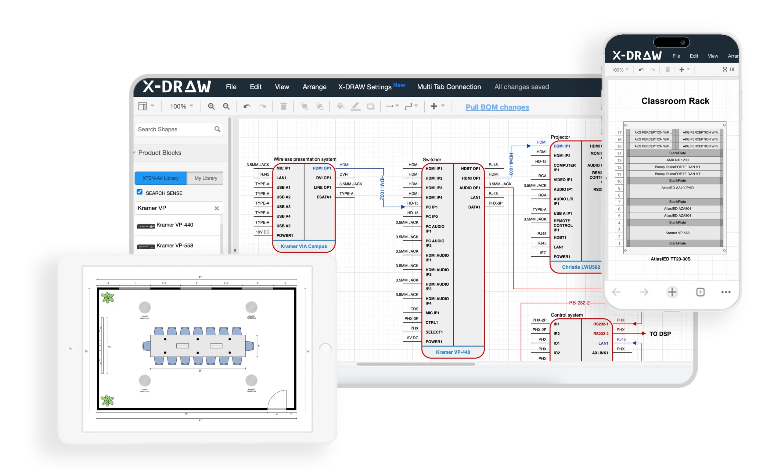
X-DRAW is a cloud-based AV design software specifically engineered for AV integrators, providing automated rack layout generation, intelligent equipment sequencing, and organization optimization based on industry best practices. Unlike generic CAD tools requiring manual rack planning, X-DRAW incorporates AV-specific logic that automatically considers weight distribution, thermal management, signal flow, and maintenance accessibility when generating rack layouts.
For wall mount rack organization, X-DRAW eliminates guesswork by analyzing equipment specifications from its extensive manufacturer database and suggesting optimal device positioning that maximizes system efficiency, reliability, and maintainability.
Key Features Enhancing Rack Organization
1. Automated Rack Layout Generation
X-DRAW automatically creates rack layouts based on equipment added to the project BOM (Bill of Materials), significantly reducing manual drafting time and minimizing design errors. Integrators can generate organized rack elevations with just a few clicks, receiving:
Optimal equipment sequencing based on weight, heat, and signal flow
Proper device spacing for thermal management
Logical positioning following AV best practices
Blank panel placement for airflow control
This automation ensures consistent rack organization across projects while incorporating thermal, structural, and signal integrity considerations automatically.
2. Intelligent Rack Elevation Diagrams
The platform generates detailed rack elevation drawings that help AV designers visualize equipment placement, spacing, airflow considerations, and installation requirements before deployment. These intelligent diagrams include:
RU position assignments optimized for equipment characteristics
Visual weight distribution showing heavy equipment at bottom
Thermal spacing indicated between heat-generating devices
Signal flow visualization through equipment sequence
Cable management requirements and positions
System designers can evaluate multiple organization strategies rapidly, selecting optimal configuration before equipment purchase.
3. Integrated BOM-to-Rack Workflow
Equipment added to the bill of materials can automatically populate rack layouts, ensuring consistency between procurement, documentation, and installation plans while reducing duplicate work. This integration provides:
Equipment specifications automatically imported from manufacturer database (weight, dimensions, power, heat)
Rack organization automatically updated when BOM changes
Thermal calculations performed automatically based on equipment power
Weight distribution verified against rack and wall capacity
Integration benefits: Specification changes propagate automatically through documentation, ensuring installers receive accurate rack organization plans matching actual equipment.
4. AV-Specific Design Automation
Unlike generic CAD platforms, X-DRAW is built specifically for AV integrators and includes AV-focused automation for rack layouts, signal flow diagrams, line schematics, and front elevation designs. The platform incorporates:
Industry best practices for equipment sequencing
Thermal management rules (spacing between heat-generating equipment)
Weight distribution algorithms (heavy equipment at bottom)
Signal flow logic (organize devices following signal paths)
Maintenance accessibility considerations (frequently serviced equipment at optimal heights)
These AV-specific rules ensure rack organizations generated by X-DRAW follow proven integration methodologies automatically.
5. Front Elevation and Rack Documentation
Users can generate automated front elevation diagrams alongside rack layouts, making it easier for installers and technicians to understand equipment positioning inside wall-mounted racks. Front elevations show:
Equipment face appearance and identification
Blank panel positions
Visual equipment relationships
Status indicator locations for monitoring
Professional installation appearance for client approval
These visualizations help stakeholders evaluate rack organization before installation, enabling design improvements when changes are easy and inexpensive.
6. Extensive Product Library
X-DRAW provides access to a large manufacturer product database, allowing designers to quickly drag, drop, and configure AV devices inside rack designs without creating components manually. The library includes:
Accurate equipment dimensions (height, width, depth) affecting rack fit
RU heights for proper spacing calculations
Weight data for load distribution planning
Power consumption specifications for thermal calculations
Heat dissipation characteristics (BTU/hr) for cooling planning
Port layouts and connectivity for cable management planning
This comprehensive equipment data enables X-DRAW to make intelligent organization recommendations based on actual device characteristics.
7. Customizable Device Blocks and Connectors
Designers can customize device blocks, connector settings, port colors, labels, and symbols, helping create cleaner and more installation-ready wall mount rack diagrams. Customization supports:
Project-specific labeling standards
Color-coded equipment by function or system
Highlighted installation notes for critical equipment
Custom equipment blocks for proprietary or specialized devices
8. Automatic Cable Labeling and Signal Management
The software automates cable labeling and signal-flow documentation, making wall mount rack planning more accurate and reducing confusion during installation and maintenance. Automated labeling provides:
Pre-generated cable labels based on signal flow
Cable routing visualization through rack organization
Cable management requirements calculated from equipment connectivity
Installation instructions clarifying cable routing approach
Installation teams benefit from clear cable identification aligned with equipment organization, streamlining deployment workflows.
9. Export to Multiple Formats
Rack layouts can be exported in formats such as PDF, PNG, SVG, Visio, AutoCAD, XML, and HTML, simplifying collaboration with consultants, contractors, and clients. This flexibility supports:
PDF exports for installer field documentation
PNG images for client presentations and approvals
AutoCAD integration for architectural coordination
HTML views for mobile-accessible rack diagrams on job sites
XML for integration with project management systems
10. Cloud-Based Collaboration
Because X-DRAW operates on a cloud platform, multiple stakeholders can review, update, and manage rack designs from anywhere, improving project coordination and version control. Cloud collaboration enables:
Design teams and installation supervisors reviewing rack organization collaboratively
Client approval of equipment layouts before installation
Real-time updates to rack plans accessible to entire project team
Mobile access to rack diagrams during installation
Centralized documentation ensuring installer access to latest plans
11. AI-Assisted Drawing Capabilities
The platform includes AI-powered drawing features that can automate design modifications, cable adjustments, and layout refinements, helping AV teams accelerate rack planning workflows. AI assistance in rack organization includes:
Intelligent equipment sequencing recommendations optimizing thermal, weight, and signal flow considerations simultaneously
Design optimization suggestions improving maintenance accessibility
Best practice enforcement ensuring industry standards compliance
Cable routing complexity assessment helping integrators identify challenging installations
Alternative layout generation enabling rapid design iteration
AI-powered organization helps less experienced designers leverage industry expertise encoded in X-DRAW algorithms.
12. Faster Revisions and Project Updates
When project requirements change, designers can quickly update rack layouts and synchronize documentation, avoiding the lengthy redraw process common in traditional CAD-based workflows. This agility supports rack organization through:
Equipment substitutions automatically repositioned for optimal organization
Equipment additions intelligently inserted at appropriate rack positions
Instant recalculation of thermal loads and weight distribution
Automatic documentation updates across all project deliverables
Revision efficiency ensures installers always work from current, accurate rack organization plans despite evolving project requirements.
Pros of X-DRAW for Rack Organization
Advantages for AV integration firms:
Optimized layouts: Automated equipment sequencing incorporating multiple best practices simultaneously
Reduced planning time: Hours of manual rack planning reduced to minutes
Consistent quality: Every rack layout follows proven organization methodologies
Thermal optimization: Automatic heat load calculation and spacing recommendations
Error prevention: Weight distribution and thermal issues identified before installation
Better documentation: Professional rack elevations improving installer guidance
Client confidence: Visual rack organization demonstrations during design phase
Knowledge capture: Best practices encoded in software accessible to entire team
Collaboration efficiency: Cloud platform enabling team-based rack planning
Cons and Considerations
Potential limitations:
Learning curve: Design teams require training on platform workflows
Subscription cost: Ongoing expense for software access
Internet requirement: Cloud platform needs reliable connectivity
AV-specific focus: Purpose-built for AV rather than general CAD applications
Database dependency: Equipment not in library requires manual entry
Best For
X-DRAW is ideally suited for:
AV integration firms seeking rack organization consistency and optimization
System designers managing multiple wall mount rack projects concurrently
Organizations standardizing equipment organization methodologies
Teams pursuing design-to-installation workflow improvement
Integrators prioritizing thermal management and system reliability
Firms seeking competitive advantage through design automation
Training environments teaching rack organization best practices

Frequently Asked Questions
What is the best order to organize equipment in a wall mount rack?
Organize equipment bottom-to-top: Heaviest devices at bottom (weight management), heat-generating equipment in lower sections (heat rises naturally), signal flow logic (sources → processing → distribution), frequently accessed equipment at comfortable heights (48-72" from floor), blank panels for spacing and airflow control.
How much space should I leave between equipment for cooling?
Maintain minimum 1U spacing between high-heat devices (>100W). Very high-heat equipment (>200W) benefits from 2U spacing. Low-heat devices (<50W) can mount consecutively. Always install blank panels in unused spaces to direct airflow through equipment rather than around it.
Should heavy equipment go on top or bottom of the rack?
Always position heaviest equipment near rack bottom. This minimizes wall stress at upper mounting points, prevents top-heavy instability, and reduces risk of mounting failure. Typical guideline: devices >20 lbs in bottom third, 10-20 lbs in middle, <10 lbs at top.
How do I decide where to position my PDU in the rack?
Rear-mounted vertical PDU on left or right side optimizes front rack space for equipment while enabling organized power cord routing. This position keeps power cords separated from signal cables and provides easy access. Alternative: horizontal PDU at rack bottom in 1-2U space offers good outlet visibility.
What is the proper way to organize cables in a wall mount rack?
Install vertical cable managers before equipment mounting. Separate cables by type (power, video, network, audio, control). Route power cables minimum 6" from signal cables. Use horizontal organizers between equipment layers. Create 12-18" service loops stored in vertical managers. Label all cables at both ends. Secure with velcro straps (not zip ties).
How can I tell if my rack needs active cooling (fans)?
Calculate total equipment power consumption. Passive ventilation (perforated doors/panels) suffices for loads <200-300W. Install cooling fans when: Equipment exceeds 300W total, using solid enclosure doors, rack in confined space, high-heat devices (amplifiers) present, or measured temperatures exceed 95°F at equipment surfaces.
Should I organize equipment by signal flow or by heat generation?
Prioritize heat management first (prevents equipment failures), then incorporate signal flow logic within thermal constraints. Example: If signal flow suggests high-heat amplifier at top but thermal management requires bottom placement, prioritize bottom placement and route cables accordingly. AI-powered design tools like X-DRAW optimize both simultaneously.
How much rack space should I reserve for future expansion?
Reserve 20-30% total rack capacity for future growth. Position reserved space near related equipment (e.g., reserve 2U near video switcher for potential input card expansion). Install blank panels in reserved positions. Verify power and cooling capacity supports future equipment. Document reserved space purpose in as-built drawings.
What's the best way to label equipment and cables in a rack?
Use a professional label printer (Brother P-Touch, DYMO) creating durable labels. For equipment: Label front panel and rear panel with device name and function. For cables: Label both ends using format "SOURCE-DEVICE-PORT → DEST-DEVICE-PORT". Place labels within 6" of connectors, visible without moving cables. Create label legend in system documentation.
How do I organize a rack when equipment doesn't follow signal flow order?
Real-world installations often require compromise. Prioritize: 1) Weight distribution (heavy at bottom - structural safety), 2) Thermal management (heat spacing - reliability), 3) Maintenance access (frequently serviced equipment at optimal heights - operational efficiency), 4) Signal flow (minimize cable complexity - installation cost). Well-planned cable management can accommodate non-linear signal flow when necessary.
Conclusion
Strategic equipment organization within wall mount Audio Visual (AV) racks represents a fundamental competency that distinguishes professional AV integrators from amateurs. Proper rack organization transcends simple equipment mounting—it requires systematic application of thermal management principles, structural engineering, signal flow logic, maintenance accessibility planning, and professional cable management practices working in harmony to create reliable, efficient, maintainable AV systems.
By following the comprehensive organization methodologies outlined in this guide—from pre-planning equipment assessment and strategic device sequencing through cable management implementation and thermal optimization—AV integration teams can consistently deliver rack deployments that maximize system reliability, minimize maintenance costs, and demonstrate the professional craftsmanship clients expect and deserve.
The rack organization process demands balancing multiple, sometimes competing priorities: positioning heavy equipment at bottom for structural stability while managing heat-generating devices for optimal thermal performance; sequencing equipment following logical signal flow while ensuring frequently accessed devices occupy comfortable working heights; implementing comprehensive cable management without obstructing critical airflow paths. Success requires systematic planning, industry knowledge, and attention to detail throughout the design-to-installation workflow.
Modern AV design automation tools like XTEN-AV's X-DRAW platform elevate rack organization from art to science, incorporating best practices, thermal calculations, weight distribution analysis, and signal flow optimization into intelligent, automated layout generation. These design platforms enable even less experienced designers to produce optimized rack organizations that previously required years of field experience, while accelerating planning workflows and improving documentation quality for entire integration teams.
Common organization mistakes—inadequate thermal spacing, improper weight distribution, chaotic cable management, poor maintenance accessibility—create expensive service callbacks, equipment failures, and client dissatisfaction that damage integrator reputations and profitability. Conversely, well-organized racks reduce installation time, accelerate troubleshooting, extend equipment lifespan, and create impressive visual presentations that build client confidence and generate referrals.
As AV systems continue growing in complexity—incorporating higher equipment densities, more sophisticated thermal requirements, increased cable management challenges, and greater system integration demands—mastering professional rack organization becomes increasingly essential for AV integration firms seeking to maintain competitive advantage, deliver consistent quality, and build lasting success.
Whether you're an experienced system designer refining organization methodologies, an installation technician seeking to improve deployment quality, or an AV integration firm establishing company-wide standards, applying the systematic approaches, best practices, and optimization techniques outlined in this comprehensive guide ensures your wall mount AV rack organizations deliver the technical excellence, operational efficiency, and professional presentation that define industry-leading AV integration services.