How Accurate Should an AV Schematic Diagram Be for Installation?
Direct Answer: An AV schematic diagram for installation should be accurate enough to ensure technicians can complete work without callbacks, typically requiring 95-98% accuracy in critical elements: device specifications, connection details, cable types, signal paths, and physical locations. This precision level prevents field errors while remaining practical for real-world installation workflows.
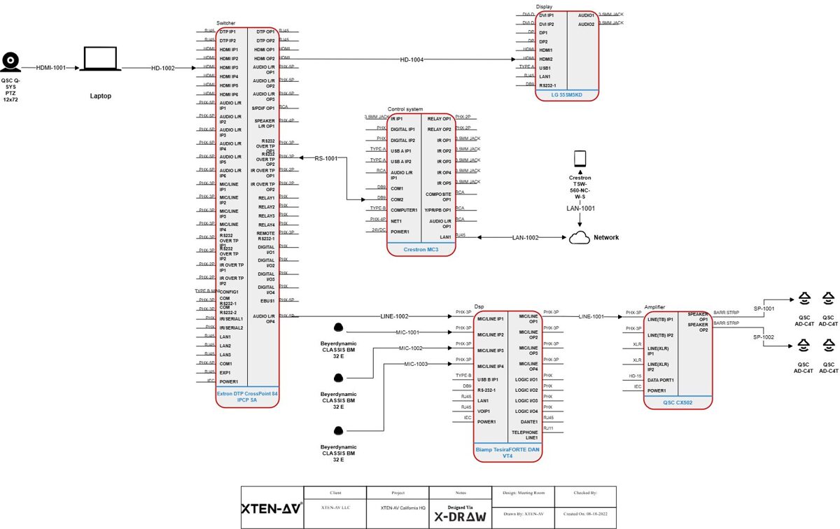
The quality of your schematic drawings begins with your design tools. Modern AV Schematic Drawing Software like XTEN-AV X-DRAW automates accuracy through integrated product databases, automated validation, and intelligent documentation generation, reducing human error that plagues manual methods. Choosing the best AV Schematic Drawing Software isn't just about drawing capabilities—it's about ensuring the accuracy standards required for successful installations
.Installation accuracy failures cost the industry millions annually through:
- Incorrect equipment orders requiring rush replacements (adding 15-30% to costs)
- Field modifications consuming 3-5x the labor of proper first-time installation
- Commissioning delays extending project timelines by weeks
- Warranty complications when improper connections damage equipment
- Client dissatisfaction damaging reputation and referral potential
Understanding AV Schematic Diagram Types and Their Accuracy Requirements
The Hierarchy of AV Documentation Precision
Not all schematic diagrams require identical accuracy levels. Different document types serve distinct purposes throughout the project lifecycle:System Block Diagrams (Conceptual Accuracy: 85-90%)
Purpose: High-level system architecture for client presentations and initial design approval.Required Accuracy:
- Signal flow paths: General direction and processing stages
- Major equipment categories: Displays, processors, control systems
- System zones: Audio, video, control subsystems
- General connectivity: Types of signals between devices
- Exact equipment models (finalized during detailed design)
- Specific cable types (determined in implementation phase)
- Precise port assignments (specified in detailed diagrams)
Signal Flow Diagrams (Technical Accuracy: 92-95%)
Purpose: Detailed signal routing for engineering validation and system integration planning.Required Accuracy:
- Device models with specific I/O configurations
- Signal types (HDMI, SDI, analog audio, Dante, etc.)
- Processing stages (scaling, switching, mixing, DSP)
- Format conversions and signal transformations
- Resolution and quality parameters
- Physical cable routing (addressed in installation drawings)
- Exact cable lengths (specified in cable schedules)
- Rack mounting positions (detailed in rack elevations)
Connection Diagrams (Installation Accuracy: 95-98%)
Purpose: Field installation guidance for technicians making physical connections.Required Accuracy:
- Exact device models and part numbers
- Specific port assignments (Input 1, Output 3, etc.)
- Cable types and specifications (Cat6a, HDMI 2.1, etc.)
- Connector types and gender (male/female)
- Pin configurations for custom cables
- Cable labels matching physical installations
- No ambiguity in connections—technicians must know exactly what connects where
- Complete specifications preventing incorrect cable or connector selection
- Clear labeling enabling cable identification during installation and service
Rack Elevation Drawings (Physical Accuracy: 98-99%)
Purpose: Equipment mounting and physical installation specifications.Required Accuracy:
- Exact equipment models with accurate RU heights
- Mounting positions (specific RU locations)
- Equipment depths for rack compatibility
- Power requirements and circuit assignments
- Cable entry points and patch panels
- Blank panels and spacers for cooling
- Equipment orientation (front/rear mounting)
- Physical fit validation—ensuring all equipment actually mounts in allocated space
- Weight distribution for rack stability
- Thermal management with adequate airflow
- Service access for maintenance and troubleshooting
Cable Schedules (Installation Accuracy: 99-100%)
Purpose: Cable procurement, fabrication, and installation specifications.Required Accuracy:
- Exact cable types with manufacturer specifications
- Precise lengths including slack and routing allowances
- Specific connectors with part numbers
- Complete labels for both ends of every cable
- Source and destination devices and ports
- Pin configurations for custom assemblies
- Testing requirements and specifications
- Absolute precision—incorrect specifications result in cables that don't work or must be replaced
- Complete data—missing information stops installation
- Clear organization—enables efficient cable pulling and termination
Key Elements That Demand Absolute Accuracy
Non-Negotiable Precision Points in AV Schematics
Certain schematic elements require absolute accuracy regardless of diagram type:1. Device Specifications and Part Numbers
Why Critical: Equipment procurement depends on exact specifications. Incorrect models result in:- Incompatible devices that don't integrate with other equipment
- Missing features that fail to meet system requirements
- Wrong form factors that don't fit intended spaces
- Ordering delays when corrections require expedited shipping
- Use AV Schematic Drawing Software with integrated product databases (like XTEN-AV X-DRAW)
- Verify specifications directly from manufacturer datasheets
- Double-check part numbers before finalizing documentation
- Lock approved equipment after client sign-off
- Maintain approved equipment lists (AEL) for all projects
2. Signal Types and Formats
Why Critical: Signal compatibility determines whether connections actually work:- HDMI 1.4 can't carry 4K60 4:4:4 signals requiring HDMI 2.0
- Analog audio requires different cabling than Dante or AES67
- SDI video needs proper cable types for distance and resolution
- Control protocols (RS-232, CEC, IR, IP) require specific connectivity
- Document signal formats explicitly (resolution, frame rate, color depth)
- Validate compatibility throughout signal chain
- Use automated validation in design software
- Specify cable types appropriate for signal requirements
- Test assumptions during design phase, not installation
3. Cable Specifications
Why Critical: Cable performance determines signal quality and system reliability:- Insufficient category (Cat5e vs. Cat6a) limits bandwidth or distance
- Wrong impedance (50Ω vs. 75Ω) causes signal degradation
- Inadequate shielding introduces interference
- Incorrect plenum rating violates code requirements
- Wrong fiber type (multimode vs. singlemode) limits distance or bandwidth
- Specify complete cable details: type, category, shielding, rating
- Calculate lengths with slack allowances (typically 10-15%)
- Include environmental requirements (outdoor, plenum, riser)
- Use automated cable scheduling from design software
- Verify specifications against distance and bandwidth requirements
4. Power Requirements
Why Critical: Electrical safety and system reliability depend on accurate power specifications:- Circuit overloads trip breakers during operation
- Insufficient ampacity causes voltage drops affecting equipment
- Wrong voltages (110V vs. 220V) damage equipment or require costly transformers
- Missing power considerations delay installation
- Specify exact power requirements for each device
- Calculate total loads for each circuit and rack
- Include power sequencing requirements
- Document voltage requirements (120V, 230V, 48V PoE, etc.)
- Use automated power calculations in design software
5. Physical Dimensions and Mounting
Why Critical: Physical fit determines whether equipment actually installs as designed:- Depth mismatches prevent equipment from fitting in racks
- Height errors consume more RU than allocated
- Weight miscalculations risk rack stability
- Clearance issues prevent access or ventilation
- Verify dimensions from manufacturer specifications
- Account for protrusions (connectors, handles, mounting ears)
- Include clearances for airflow and service access
- Calculate total weight against rack capacity
- Use 3D visualization when available in design software
How Professional AV Schematic Drawing Software Ensures Accuracy
The Technology Foundation for Precision Documentation
Manual schematic creation introduces multiple error points: transcription mistakes, outdated specifications, calculation errors, and version control problems. Modern AV Schematic Drawing Software systematically addresses each vulnerability.XTEN-AV X-DRAW: Setting the Accuracy Standard
XTEN-AV X-DRAW stands as the best AV Schematic Drawing Software specifically because it engineered accuracy into every aspect of the design workflow:🎯 Purpose-Built AV Design Platform
X-DRAW isn't a generic CAD tool adapted for AV use—it's engineered specifically for audiovisual system design with native understanding of accuracy requirements:AV Intelligence:
- Signal type recognition automatically validates compatibility
- Device relationship understanding prevents incompatible connections
- Industry-standard symbols eliminate misinterpretation
- Pre-built templates incorporate best practices and accuracy standards
- Workflow optimization designed around integration project needs
☁️ Cloud-Based Collaboration & Accessibility
Full cloud hosting eliminates version control problems that compromise accuracy:Single Source of Truth:
- No local copies causing version confusion
- Real-time updates ensure everyone works from current design
- Automatic backup prevents data loss
- Revision tracking documents all changes with timestamps and user attribution
- Access from anywhere enables field verification and updates
📚 Extensive Integrated AV Product Database
X-DRAW's comprehensive database includes thousands of AV components with complete specifications:Accurate Device Data:
- Exact specifications directly from manufacturers
- Complete I/O configurations (ports, connectors, protocols)
- Power requirements and thermal characteristics
- Physical dimensions (width, depth, height, weight)
- Regular updates as manufacturers release new products or revisions
- Search and select products without manual data entry
- Specifications automatically populate schematics and documentation
- No transcription errors from manual typing
- Consistent naming across all project documents
🤖 Automation & AI-Assisted Design
Intelligent automation accelerates workflows while improving accuracy:Auto Cable Labeling and Routing:
- Consistent naming conventions applied automatically
- Bidirectional labels for both cable ends
- Signal type indicators in label schemes
- Length calculations based on routing paths
- Organized schedules generated instantly
- Compatibility suggestions based on system requirements
- Alternative product recommendations maintaining specifications
- Signal path optimization for performance
- Error detection before installation
- Bills of materials with accurate quantities from design
- Cable lists with complete specifications
- Signal flow diagrams reflecting actual connections
- Rack layouts with proper equipment placement
📐 Rich Drawing Tools & Flexible Editing
Dynamic drawing capabilities support accurate system representation:Intelligent Design Tools:
- Drag-and-drop components with specifications attached
- Smart connectors reflecting real-world signal paths
- Signal type validation during connection creation
- Custom device blocks for specialty equipment
- Multi-level detail from overview to installation specifics
- Color coding by signal type
- Layer management separating system types
- Annotation tools for specifications and notes
- Zoom and detail views for complex areas
📄 Automated Documentation
X-DRAW automatically generates installation-ready documentation:Bills of Materials (BOM):
- Accurate quantities calculated from design
- Complete specifications with manufacturer part numbers
- Category organization for procurement efficiency
- Pricing integration for cost tracking
- Revision tracking as design evolves
- Multi-level detail from system overview to device ports
- Format specifications at each processing stage
- Validation indicators showing compatibility verification
- Professional presentation for client deliverables
- Front and rear elevations with accurate equipment representation
- RU allocation matching actual equipment heights
- Power consumption summaries for circuit planning
- Thermal considerations with proper spacing
- Service access planning
- Connection details with exact port assignments
- Cable specifications matching procurement
- Testing procedures and acceptance criteria
- Field-ready format for technician use
🔄 Seamless Integration with Industry Tools
Interoperability with broader project ecosystems:File Format Support:
- AutoCAD DWG import/export for architectural coordination
- Microsoft Visio compatibility for stakeholder review
- PDF generation with accurate scaling
- Excel/CSV export for BOMs and schedules
- CRM connectivity for project tracking
- Estimation software links for pricing
- Project management tool integration
- API access for custom workflows
🧩 Customization & Templates
Standardization capabilities improve consistency:Pre-Configured Templates:
- Proven designs for common project types
- Accurate specifications built into templates
- Standard nomenclature across projects
- Best practices embedded in workflows
- Custom symbols and graphics
- Naming conventions enforcement
- Drawing standards matching corporate style
- Reusable components for recurring elements

Step-by-Step Process: Creating Installation-Accurate Schematics
Systematic Workflow for Precision Documentation
Phase 1: Requirements Gathering and Validation
Step 1: Document Functional Requirements- User needs and operational scenarios
- Performance expectations (resolution, audio quality, coverage)
- Integration requirements with existing systems
- Budget constraints and priorities
- Room dimensions and acoustics
- Equipment locations and mounting options
- Cable pathways and distances
- Power availability and electrical infrastructure
- Network infrastructure capacity
- Naming conventions for devices and cables
- Drawing formats and styles
- Approval workflows and revision processes
- Deliverable requirements for stakeholders
Phase 2: System Architecture Design
Step 4: Select Equipment Using Verified Databases Use AV Schematic Drawing Software like XTEN-AV X-DRAW to:- Search integrated product databases
- Select devices with complete specifications
- Verify compatibility across system
- Document alternative options for value engineering
- Define signal flow paths from sources to destinations
- Identify processing requirements (switching, scaling, mixing)
- Establish control architecture and user interfaces
- Validate overall system feasibility
- Specify exact device models and configurations
- Define port assignments for each connection
- Document signal formats at each stage
- Validate performance specifications end-to-end
Phase 3: Detailed Connection Design
Step 7: Design Physical Connections- Create connection diagrams showing exact port assignments
- Specify cable types appropriate for signals and distances
- Define connector types and configurations
- Label every connection with unique identifiers
- Identify cable pathways from architectural drawings
- Calculate cable lengths including routing and slack
- Specify cable management (conduit, tray, dress)
- Document special requirements (plenum, outdoor, shielding)
- Complete cable list with types and lengths
- Label specifications for both ends
- Connector details and assembly notes
- Testing requirements for each cable type
Phase 4: Physical Layout Design
Step 10: Design Equipment Racks- Allocate RU space for each device
- Verify equipment depths against rack capacity
- Calculate power requirements and circuit assignments
- Plan cable access and patch panels
- Ensure thermal management with proper spacing
- Show equipment locations on floor plans
- Specify mounting methods and hardware
- Document access requirements for service
- Identify integration points with architectural elements
Phase 5: Documentation Generation and Review
Step 12: Generate Complete Documentation Set Using automated tools in professional software:- Bill of Materials with specifications and quantities
- Signal flow diagrams at multiple detail levels
- Connection diagrams for installation
- Rack elevations front and rear
- Cable schedules with complete specifications
- Installation drawings for field use
- Design review for technical accuracy
- Specification verification against requirements
- Constructability review by installation team
- Cost validation against budget
- Client review for scope confirmation
- Lock approved design preventing accidental changes
- Track revisions with dates and reasons
- Distribute controlled copies to stakeholders
- Maintain revision history for reference
Accuracy Standards by Project Type
Tailoring Precision to Project Requirements
Different project types and scales warrant adjusted accuracy approaches:Small Commercial Installations (Single Room)
Project Profile:- Conference rooms, huddle spaces
- 3-10 devices total
- Standard equipment and connectivity
- Short cable runs (<50 feet)
- Equipment specifications: 100% accuracy required
- Connection details: Complete port assignments
- Cable specifications: Full details with types and connectors
- Physical layout: General placement acceptable
- Documentation: Comprehensive but not exhaustive
Medium Commercial Projects (Multi-Room)
Project Profile:- Corporate offices, small educational campuses
- 20-100 devices across multiple rooms
- Mix of standard and custom solutions
- Coordinated systems with central infrastructure
- Equipment specifications: 100% accuracy critical
- Connection details: Complete documentation for all connections
- Cable specifications: Comprehensive schedules with routing notes
- Physical layout: Detailed rack elevations and equipment locations
- Documentation: Full professional package
Large Commercial/Institutional Projects
Project Profile:- Corporate headquarters, universities, hospitals
- 100-1000+ devices
- Complex networked AV systems
- Multiple contractors and trades
- Extended installation timelines
- Equipment specifications: 100% accuracy with formal change control
- Connection details: Exhaustive documentation including testing procedures
- Cable specifications: Complete schedules with construction coordination
- Physical layout: Detailed integration with architectural/MEP systems
- Documentation: Comprehensive packages with revisions tracked formally
Specialty Installations (Broadcast, Performance Venues)
Project Profile:- Broadcast studios, theaters, houses of worship
- Highly customized systems
- Critical performance requirements
- Complex signal processing and routing
- Equipment specifications: 100% with extensive validation
- Connection details: Pin-level accuracy for custom configurations
- Cable specifications: Complete specifications including impedance, capacitance
- Physical layout: Detailed coordination with acoustic/architectural elements
- Documentation: Extensive with commissioning procedures
Common Accuracy Mistakes and How to Avoid Them
Learning from Field Experience
Mistake #1: Outdated Equipment Specifications
The Problem: Using obsolete specifications when products have been updated or discontinued.Real-World Impact:
- Order equipment that's been discontinued
- Receive updated models with different I/O configurations
- Discover incompatibilities during installation
- Require field modifications or expedited replacements
- Use AV design software with regularly updated databases
- Verify specifications from manufacturer websites before finalizing
- Check product availability during design phase
- Maintain approved equipment lists locked after client approval
- Subscribe to manufacturer notifications for product updates
Mistake #2: Insufficient Cable Specification Detail
The Problem: Generic cable specifications like "HDMI cable" without version, length, or quality parameters.Real-World Impact:
- Receive HDMI 1.4 cables for 4K60 4:4:4 system requiring HDMI 2.0
- Inadequate length requiring splicing or extensions
- Missing features (CEC support, ARC/eARC capability)
- Quality issues causing intermittent signal problems
- Specify complete details: cable type, version, length, special features
- Include performance requirements: bandwidth, resolution support
- Document testing specifications: required certifications
- Use automated cable schedules from design software
- Validate cable specifications against signal requirements
Mistake #3: Ambiguous Connection Diagrams
The Problem: Unclear port assignments or incomplete connection details causing field confusion.Real-World Impact:
- Technicians guess which ports to use
- Incorrect connections requiring troubleshooting and rework
- Equipment damage from improper signal routing
- Installation delays while seeking clarification
- Label every connection with specific port identifiers ("HDMI Input 2", not "HDMI port")
- Use unique cable identifiers on both ends
- Color-code by signal type for visual clarity
- Include port detail views for complex devices
- Provide connector pin configurations for custom cables
Mistake #4: Inaccurate Rack Elevations
The Problem: Equipment heights, depths, or mounting positions that don't match reality.Real-World Impact:
- Equipment doesn't fit in allocated space
- Insufficient depth preventing rack mounting
- Inadequate cooling from improper spacing
- Power strip conflicts with equipment placement
- Verify dimensions from manufacturer specifications (not assumptions)
- Account for protrusions: connectors, handles, mounting brackets
- Include depth measurements ensuring rack compatibility
- Plan service access requiring equipment slide-out
- Use 3D rack planning tools when available
- Calculate total weight against rack capacity
Mistake #5: Missing or Incorrect Power Specifications
The Problem: Incomplete power requirements or calculation errors in electrical planning.Real-World Impact:
- Circuit overloads during operation
- Inadequate ampacity causing voltage drops
- Wrong voltages requiring transformers or equipment replacement
- Electrical code violations failing inspection
- Document exact power requirements for every device
- Calculate total loads with 20% headroom
- Specify voltage requirements explicitly (120V, 230V, 48V PoE)
- Identify sequencing needs for equipment protection
- Use automated power calculations in design software
- Coordinate with electrician early in design process
Mistake #6: Poor Version Control
The Problem: Multiple document versions circulating without clear identification.Real-World Impact:
- Installers work from outdated drawings
- Procurement uses different specs than installation
- Conflicting information across documents
- Change orders from discrepancies
- Use cloud-based design platforms with automatic version control
- Implement formal revision procedures with approval workflows
- Clearly mark document status: Preliminary, Approved, As-Built
- Include revision dates and numbers on every drawing
- Distribute controlled copies only, not editable files
- Maintain single source of truth in project management system
The Role of AI in Improving Schematic Accuracy
How Artificial Intelligence Enhances Precision
AI integration in modern AV design software represents a fundamental shift in how accuracy is achieved and maintained:Automated Validation and Error Detection
AI-Powered Checking:- Signal compatibility validation throughout design
- Distance limitation checking for cable types
- Bandwidth calculations for network infrastructure
- Power consumption totals and circuit validation
- Physical fit verification in rack designs
- "HDMI 1.4 cannot support 4K60 at this resolution—recommend HDMI 2.0"
- "Cat5e cable exceeds maximum length for 10Gbps—use Cat6a or add switch"
- "Total rack power (18.5A) approaches circuit capacity (20A)—consider load balancing"
- "Equipment depth (28") exceeds rack capacity (24")—verify mounting options"
Intelligent Product Recommendations
Context-Aware Suggestions: Machine learning analyzes project requirements to recommend:- Optimal equipment for performance and budget
- Compatible components validated across system
- Alternative options when preferred products unavailable
- Updated models when current selections obsolete
- Latest product data from manufacturer databases
- Correct I/O configurations for selected models
- Accurate specifications for all parameters
- Compatibility verified across interconnected devices
Predictive Error Prevention
Pattern Recognition: AI analysis of thousands of designs identifies:- Common error patterns specific to project types
- Compatibility issues frequently overlooked
- Installation challenges from certain design decisions
- Best practices from successful projects
- "Similar conference rooms typically include wireless presentation—consider adding"
- "This display placement creates cable routing challenges—alternative location recommended"
- "Projects with this processing load often require additional cooling—verify thermal planning"
Automated Documentation Quality Assurance
Consistency Checking: AI validates that information matches across documents:- BOM specifications match connection diagrams
- Cable schedules reflect actual connections in schematics
- Rack elevations show same equipment as signal flow diagrams
- Power requirements consistent across rack layouts and electrical plans
- All devices have power specifications
- Every connection appears in cable schedule
- All equipment allocated in rack elevations
- Complete information for procurement and installation
Best Practices for Maintaining Schematic Accuracy
Systematic Approaches to Precision
Establish Company Standards
Standardization Framework:- Naming conventions for devices, cables, racks
- Drawing formats and templates
- Specification requirements for documentation
- Review processes before release
- Change control procedures
- Required information for each document type
- Level of detail appropriate for audience
- File naming and version control
- Archival procedures for completed projects
Implement Quality Control Checkpoints
Design Review Gates:- Preliminary review: Validate system architecture and equipment selection
- Detailed review: Verify connections, specifications, and documentation
- Constructability review: Confirm installability with field team
- Pre-installation review: Final check before material procurement
- All equipment has complete specifications and part numbers
- Every connection shows exact ports and cable types
- Cable schedule includes all connections with complete specifications
- Rack elevations show accurate equipment dimensions and mounting
- Power requirements documented for all devices and totaled by circuit
- BOM matches equipment in all drawings
- Revisions tracked with dates and descriptions
- Client approval documented for scope and equipment
Leverage Technology for Accuracy
Use Professional AV Design Software: Platforms like XTEN-AV X-DRAW automate accuracy:- Integrated databases eliminate manual specification entry
- Automated documentation ensures consistency across deliverables
- Validation tools check compatibility and specifications
- Version control maintains single source of truth
- Cloud collaboration ensures everyone works from current version
- Automated checking of signal compatibility
- Calculation validation for power, bandwidth, cable lengths
- Physical fit verification in rack designs
- Performance simulation where available
Maintain Current Product Knowledge
Stay Informed:- Subscribe to manufacturer updates for product changes
- Attend industry training on new technologies
- Participate in user groups sharing best practices
- Review design software updates for new features
- Update internal libraries with current products
- Regular updates of product specifications
- Removal of obsolete equipment from templates
- Addition of new products as released
- Verification of specifications periodically
Frequently Asked Questions (FAQ)
1. How accurate do cable lengths need to be in schematic diagrams?
Cable length accuracy depends on the documentation type and project phase:During Design Phase:
- Estimated lengths based on routing paths are acceptable
- Include 10-15% slack allowance for routing variations
- Use architectural drawings for distance calculations
- Round up to standard cable lengths (3ft, 6ft, 10ft, 25ft, 50ft, etc.)
- Sufficient accuracy to order correct lengths without waste
- Over-estimate by 10-15% rather than under-estimate
- Consider standard increments for cost efficiency
- Factor service loops and management requirements
- Precise enough for technicians to plan pulling
- Include notes on routing challenges or special requirements
- Specify where exact measurement required (custom fabrications)
- Document slack requirements at termination points
When Exact Precision Matters:
- Custom cable fabrications requiring exact lengths
- Patch cables in dense rack environments
- Ceiling cable with limited accessibility for corrections
- Structured cabling requiring certified testing
2. Should schematics show as-designed or as-installed configurations?
Different schematic versions serve distinct purposes:As-Designed (Pre-Installation): Purpose: Guide installation based on planned configuration
Characteristics:
- Shows intended equipment and connections
- Uses planned cable routing paths
- Reflects approved scope and specifications
- Marked clearly as "For Construction" or "For Installation"
As-Built (Post-Installation): Purpose: Document actual installation for service and maintenance
Characteristics:
- Shows actually installed equipment (including field substitutions)
- Reflects actual cable routing and connections
- Includes field modifications and changes
- Documents actual cable labels and identification
- Marked clearly as "As-Built" or "Record Drawings"
Best Practice:
- Create as-designed schematics for installation
- Redline during installation to document changes
- Generate as-built documentation incorporating field modifications
- Archive both versions for future reference
- Deliver as-built drawings to clients as project deliverable
3. How do I balance detail level with diagram readability?
Excessive detail creates overwhelming diagrams that technicians can't interpret quickly. Insufficient detail leaves ambiguity causing errors. The balance:Use Hierarchical Documentation:
Level 1: System Block Diagram
- High-level overview for understanding system architecture
- Major components and signal flow
- Subsystem boundaries
- Minimal detail focusing on concepts
- Detailed equipment specifications
- Connection types and signal formats
- Processing stages and transformations
- Moderate detail for engineering validation
- Exact port assignments and cable types
- Physical routing information
- Testing requirements
- Maximum detail for field work
- One diagram type = one purpose—don't mix overview and detailed installation info
- Use references between diagrams ("see Sheet 3 for detailed connections")
- Layer information allowing readers to drill down as needed
- Consistent symbols and conventions across all drawings
- Clear legends explaining notation and abbreviations
- Generate overview diagrams automatically
- Create detailed connection views for installation
- Produce specification sheets for procurement
- Maintain consistency across all views
4. What's the best way to handle design changes without compromising accuracy?
Design changes are inevitable, but managing them systematically maintains accuracy:Formal Change Control Process:
Step 1: Document Change Request
- Originator and date
- Reason for change (client request, field condition, value engineering)
- Scope of change (affected systems/equipment)
- Cost and schedule impact
- Compatibility with unchanged portions
- Performance implications
- Specification changes required
- Documentation updates needed
- Design team review for technical accuracy
- Project manager approval for cost/schedule
- Client approval for scope changes
- Contractor notification of impacts
- Revise drawings in design software
- Regenerate automated documents (BOM, cable schedules)
- Update revision tracking with description of change
- Distribute revised documents with change highlighted
- Archive superseded versions without deletion
- Single design database automatically updates all generated documents
- Version control tracks changes with timestamps and users
- Revision comparison shows exactly what changed
- Automated redistribution notifies stakeholders of updates
- No version proliferation from emailed file attachments
5. How should I document custom or specialty equipment not in standard databases?
Custom devices require special handling to maintain accuracy:Documentation Requirements:
- Complete specifications as if manufacturer data sheet
- Physical dimensions (width, depth, height, weight)
- I/O configuration (ports, connectors, pinouts)
- Power requirements (voltage, current, connector type)
- Signal specifications (formats, impedances, levels)
- Mounting details (rack ears, wall bracket, table stand)
In AV Design Software:
- Create custom device block with specifications
- Define connection points (inputs, outputs)
- Specify signal types for each port
- Add to personal library for reuse
- Document source of specifications (custom fabrication drawings, vendor quotes)
- Attach specification documents to project files
- Include vendor contact information for future reference
- Create as-built photos documenting actual device
- Maintain specification library for frequently used custom items
- Double-check custom specifications—no database validation available
- Verify with fabricator/vendor before finalizing documentation
- Test fit custom equipment in mock-ups when possible
- Document assumptions that require field verification
- Custom device creation with complete specifications
- Library storage for organizational reuse
- Same automation (BOMs, cable schedules) as standard products
- Integration with overall system design
6. What level of accuracy is needed for as-built documentation?
As-built documentation requires absolute accuracy because it serves as the permanent record for:- System troubleshooting over system lifespan
- Future modifications and upgrades
- Service and maintenance
- Regulatory compliance documentation
- Facility management records
- Actually installed equipment (including field substitutions)
- Actual cable routing and infrastructure used
- Actual cable labels and identification system
- Actual configurations of programmable devices
- Field modifications to original design
- Actual rack layouts with equipment positions
- Actual network addressing (IP addresses, VLANs, switch ports)
- Redline drawings during installation with field changes
- Photograph installations for reference
- Document cable labels as actually applied
- Record configurations from commissioned systems
- Update design documents with all changes
- Regenerate documentation from updated design
- Verify accuracy with installation team
- Deliver to client as final project deliverable
- Delivering as-designed drawings without field updates
- Incomplete redlining missing key changes
- Assuming "close enough" for troubleshooting later
- Not documenting IP addresses and network configuration
- Omitting field modifications from permanent record
- Budget as-built documentation time in project planning
- Assign responsibility for redlining to specific team member
- Use photo documentation throughout installation
- Update design software with all changes
- Quality check as-builts against field conditions before delivery
7. How does schematic accuracy affect project profitability?
Accuracy directly impacts profitability through multiple mechanisms:Cost of Inaccuracy:
Material Waste:
- Incorrect equipment orders: 5-15% of equipment costs
- Wrong cable types/lengths: 10-20% of cable costs
- Rush shipping for corrections: 50-200% premium
- Total material waste: typically 8-12% of material budget
- Field corrections: 3-5x time vs. correct first time
- Troubleshooting: 2-4 hours per error discovered
- Rework: complete connection redo required
- Total labor impact: 15-25% labor budget overrun
- Waiting for corrections: 3-7 days typical
- Cascading impacts: delaying other trades
- Liquidated damages: contractual penalties
- Opportunity cost: delayed invoicing and payment
Project with Inaccurate Documentation:
- Material costs: $50,000
- Material waste (10%): $5,000
- Labor hours: 400 hours @ $75/hr = $30,000
- Labor overrun (20%): $6,000
- Schedule delay costs: $3,000
- Total accuracy cost: $14,000 (19% of project budget)
- Material costs: $50,000
- Material waste (1%): $500
- Labor hours: 400 hours @ $75/hr = $30,000
- Labor efficiency (0% overrun): $0
- Schedule performance bonus: $2,000 credit
- Net accuracy benefit: $15,500 profit improvement
- Software cost: $200/month = $2,400/year
- Time savings: 150 hours/year @ $75/hr = $11,250
- Error reduction: $8,000/year avoided costs
- Net ROI: $16,850 benefit / $2,400 cost = 702% ROI
Conclusion: Key Takeaways for Installation-Accurate Schematics
Building a Foundation for Installation Success
Schematic accuracy isn't an abstract quality goal—it's the determinant of installation efficiency, project profitability, and long-term system maintainability. The 95-98% accuracy standard for installation documentation represents the threshold where field work proceeds smoothly without costly corrections.
Essential Principles
✅ Different Documents Require Different Accuracy Levels Block diagrams communicate concepts (85-90%), signal flows validate engineering (92-95%), while installation diagrams and cable schedules demand near-perfection (95-100%). Match precision to purpose.✅ Critical Elements Demand Absolute Accuracy Equipment specifications, signal types, cable details, power requirements, and physical dimensions require 99-100% accuracy—errors directly cause procurement mistakes and installation failures.
✅ Professional Software Ensures Systematic Accuracy XTEN-AV X-DRAW and similar purpose-built platforms eliminate manual transcription errors through integrated databases, automated documentation, and intelligent validation, achieving accuracy levels impossible with manual methods.
✅ Version Control Is Non-Negotiable Cloud-based platforms eliminate version proliferation causing installers to work from outdated drawings. Single source of truth prevents the costly errors from documentation confusion.
✅ AI Validation Catches Errors Humans Miss Automated compatibility checking, calculation validation, and specification verification systematically review every detail, catching problems before they reach the field.
✅ As-Built Documentation Completes the Accuracy Cycle Record drawings reflecting actual installations serve future service and modifications. Incomplete or inaccurate as-builts create permanent maintenance challenges.
✅ Accuracy Delivers Measurable ROI The cost of inaccuracy (material waste, labor inefficiency, schedule delays) typically exceeds 15-20% of project budget. Investing in accuracy tools and processes returns 5-10x through error elimination.
Action Steps for Immediate Improvement
For Integration Firms:- Evaluate current accuracy levels: Measure material waste and field correction rates
- Invest in professional AV design software: Tools like XTEN-AV X-DRAW pay for themselves within 2-3 projects
- Establish documentation standards: Define accuracy requirements for each document type
- Implement quality control: Multi-level review before releasing drawings
- Track metrics: Monitor accuracy improvements and ROI achievement
- Leverage integrated databases: Eliminate manual specification entry errors
- Use automated validation: Catch compatibility issues during design
- Generate documentation automatically: Ensure consistency across deliverables
- Maintain version control: Work from single source of truth
- Update as-built documentation: Complete the accuracy cycle
- Budget for accuracy: Allocate time and resources for proper documentation
- Enforce standards: Require compliance with established accuracy requirements
- Support quality tools: Invest in software enabling systematic accuracy
- Track costs of inaccuracy: Measure impact on project profitability
- Celebrate accuracy wins: Recognize projects with zero field corrections
The Competitive Advantage
In an industry where margins tighten and clients demand value, documentation accuracy becomes a key differentiator. Firms that deliver installation-accurate schematics experience:- Faster project completion from efficient field work
- Higher profitability from eliminated waste and rework
- Stronger client relationships from professional deliverables
- Better reputation enabling premium pricing
- Scalable operations supporting growth
Don't let documentation inaccuracy limit your project success. Evaluate your current practices against the standards in this guide, implement professional design software, and establish quality processes that make installation-accurate schematics the norm rather than the exception.